
Antiglare film, manufacturing method thereof and transmission type LCD

a technology of antiglare film and manufacturing method, which is applied in the direction of instruments, coatings, applications, etc., can solve the problems of increased material cost and number of processes, increased reflection, and decreased image recognizability, so as to improve adhesion between different layers and reduce cost

Active Publication Date: 2012-08-28
TOPPAN PRINTING CO LTD
View PDF12 Cites 0 Cited by
  • Summary
  • Abstract
  • Description
  • Claims
  • Application Information

AI Technical Summary

Benefits of technology

[0058]The antiglare film 100 provided with an antiglare layer 120 that has a low haze value in a range of 3-15% can be advantageously used as the antiglare film 100 of the embodiment of the invention. In a case where the haze value of the antiglare layer 120 exceeds 15%, sufficient contrast cannot be obtained. Furthermore, because a sufficient antiglare ability can be obtained due to a haze value of the antiglare layer 120, the effect of the invention cannot be sufficiently demonstrated. In a case where the haze value of the antiglare layer 120 is less than 3%, sufficient antiglare ability cannot be obtained.
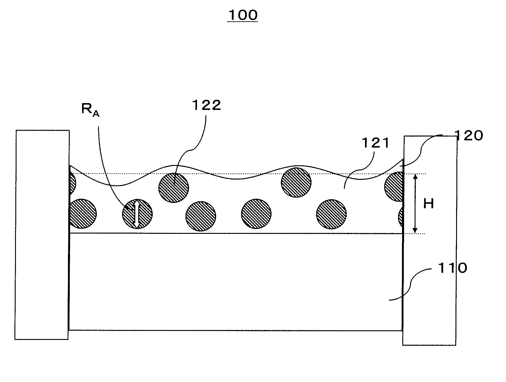
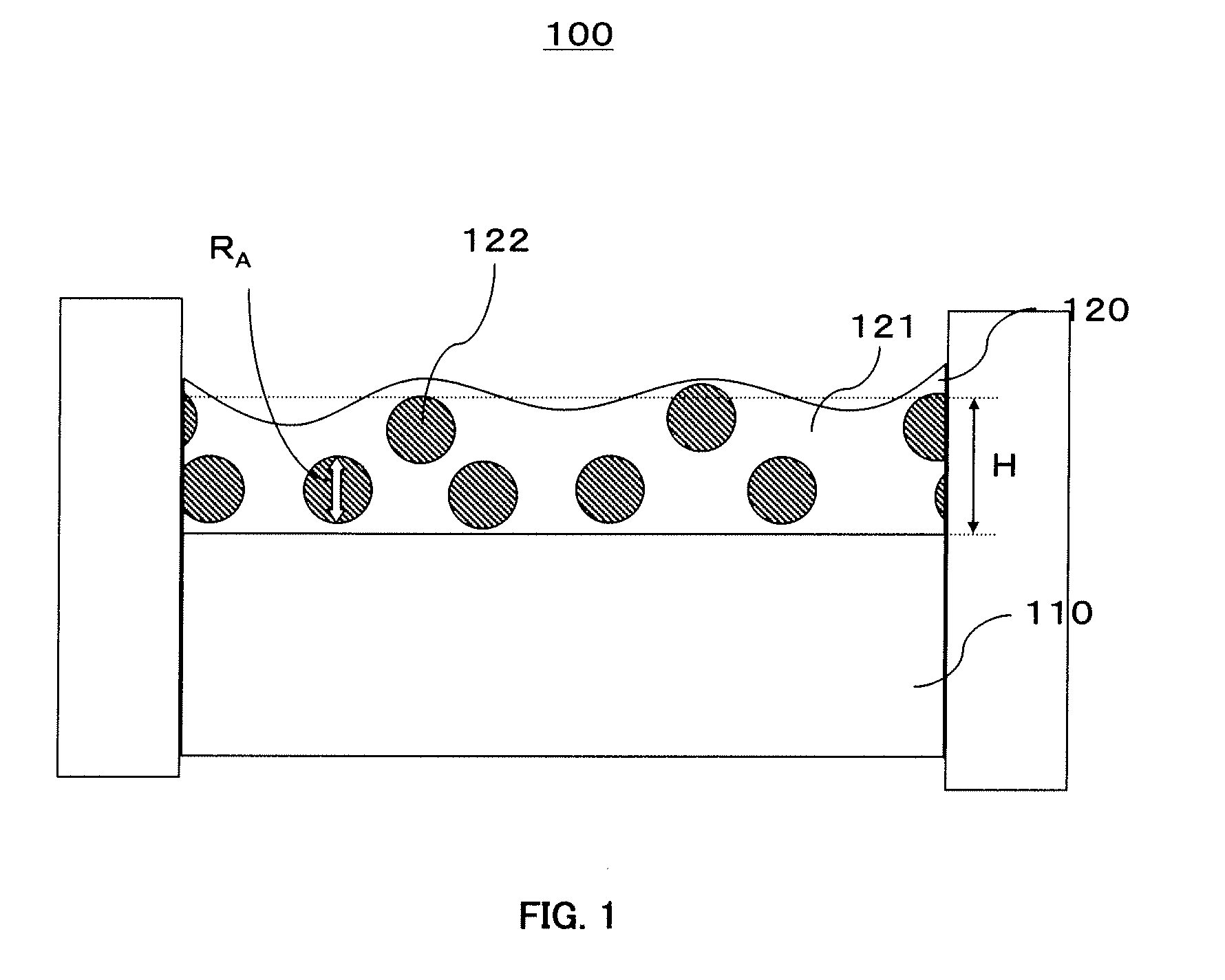
[0059]In the antiglare film 100 of the embodiment of the invention, a value RA / H, which is obtained by dividing an average diameter RA of the particles 122 contained in the antiglare layer 120 by an average thickness H of the antiglare layer 120, is preferably in the range of 0.3-0.8 and a refractive index n of the binder matrix 121 is preferably less than or equal to 1.47. The inventors have discovered that where a value RA / H, which is obtained by dividing an average diameter RA of the particles 122 contained in the antiglare layer 120 by an average thickness H of the antiglare layer 120, is in the range of 0.30-0.80, most of the surface of the antiglare layer 120 can be covered with the binder matrix 121, without the particles 122 protruding on the surface of the antiglare layer 120, and the integrated reflectance of the surface of the antiglare layer 120 can be made less than or equal to 4% by setting the refractive index n of the binder matrix 121 to a value less than or equal to 1.47.
[0060]In a case where, the value RA / H, which is obtained by dividing an average diameter RA of the particles 122 by an average thickness H of the antiglare layer 120, exceeds 0.8, the particles 122 are not covered by the binder matrix 121 and many particles 122 protrude from the antiglare layer 120. As a result, the integrated reflectance of the surface of the antiglare layer 120 is difficult to easily make less than or equal to 4% by setting the refractive index of the binder matrix 121 to a value less than or equal to 1.47. Further, in a case where the value RA / H, which is obtained by dividing an average diameter RA of the particles 122 by an average thickness H of the antiglare layer 120, is less than 0.3, a concave-convex structure is difficult to form on the surface of the antiglare layer 120.
[0061]Further, in a case where the refractive index n of the binder matrix 121 is higher than 1.47, the integrated reflectance of the surface of the antiglare layer 120 is difficult to make less than or equal to 4%. Preferably, the lower the refractive index n of the binder matrix 121, the lower the integrated reflectance of the surface of the antiglare layer 120 can be, but taking into account that the antiglare layer 120 is formed at a low cost by using the material forming the binder matrix 121, it is preferred that the refractive index n of the binder matrix 121 be in a 1.40-1.47 range. In a case where the refractive index n of the binder matrix 121 is higher than 1.47, the effect of the invention cannot be sufficiently demonstrated.
[0062]In the present embodiment of the invention, the refractive index n of the binder matrix 121 means a refractive index of the film after the film has been formed from the binder matrix 121 in a form excluding the particles 122 contained in the antiglare layer 120. The refractive index n of the binder matrix 121 can be found by a Becke line detection method (immersion method).
[0063]The antiglare film 100 of the embodiment of the invention can be provided, if necessary, with a functional layer having antistatic performance, antifouling performance, electromagnetic shield performance, infrared absorbing performance, ultraviolet absorbing performance, and color correcting performance. Such functional layers may be used individually, or a plurality of such layers may be used. A functional layer can also combine a plurality of functions in one layer. The functional layer may be provided between the first transparent substrate 110 and antiglare layer 120 or on the side of the first transparent substrate 110 opposite to the antiglare layer 120. In the embodiment of the invention, a primer layer or an adhesive layer may be provided between the layers to improve adhesion between different layers.

Problems solved by technology

The resultant problem is that reflection is increased and image recognizability is decreased.
However, the problem arising when an antireflection layer is laminated on the antiglare layer is that material cost and number of processes are increased and cost is raised, while the production yield is degraded.

Method used


Image

  • Antiglare film, manufacturing method thereof and transmission type LCD
  • Antiglare film, manufacturing method thereof and transmission type LCD
  • Antiglare film, manufacturing method thereof and transmission type LCD

Examples


example 1

[0090]Examples and comparative examples of the invention will be described below in greater detail.

[0091]As shown in FIG. 1, a triacetyl cellulose film (TD-80U, manufactured by Fuji Photo Film Co., Ltd.) was used as the first transparent substrate 100. In the coating liquid for forming the antiglare layer 120, 94.5 parts by weight of a silicone material curable by ionizing radiation, 5.0 parts by weight of Irgacure 184 (manufactured by Ciba-Geigy) as a polymerization initiator, and 0.5 part by weight of BYK 350 (manufactured by BYK Chemi Japan) as an acrylic additive were used as forming materials of the binder matrix 121. Further, acrylic particles, 10 parts by weight, with an average diameter of 5 μm and a refractive index of 1.49 were prepared as the particles 122. A mixed solvent containing 30 parts by weight of dioxolan and 70 parts by weight of toluene was used as the solvent. The components were mixed to produce a coating liquid for forming the antiglare layer 120.

[0092]The c...


PUM

PropertyMeasurementUnit
RAaaaaaaaaaa
reflectanceaaaaaaaaaa
refractive indexaaaaaaaaaa

Abstract

The invention provides an antiglare film that has a low haze value, can maintain antireflection ability, and has inhibited reflection of external light, and also provides a manufacturing method thereof, and a transmission type liquid crystal display. The antiglare film includes a transparent substrate and an antiglare layer, wherein the antiglare layer is formed on the transparent substrate, has a concave-convex structure on the opposite surface of the antiglare layer from the transparent substrate, and includes a binder matrix and particles, the integrated reflectance of the antiglare layer at a wavelength of 550 nm is less than or equal to 4%, and a haze value of the antiglare layer is in the range of 3-15%.

Description

CROSS REFERENCE TO RELATED APPLICATION[0001]This application is based on and claims the benefit of priority from the Japanese Patent Application No. 2008-246819, filed on Sep. 25, 2008, the entire contents of which are incorporated herein by reference.BACKGROUND OF THE INVENTION[0002]1. Field of the Invention[0003]The present invention relates to an antiglare film, a manufacturing method thereof, and a transmission type liquid crystal display. In particular, the invention relates to an antiglare film that can be provided on the surface of a window or a display such as a liquid crystal display (LCD), a CRT display, an organic electroluminescence display (ELD), a plasma display (PDP), a surface emission display (SED), and a field emission display (FED).[0004]2. Description of the Related Art[0005]In the field of displays such as liquid crystal displays, CRT displays, EL displays, and plasma displays, an antiglare film having a concave-convex structure on the surface is known to be pro...

Claims


Application Information

Patent Timeline
Patent Type & Authority Patents(United States)
IPC IPC(8): G02F1/1335
CPCB29D11/00865G02B5/0226G02B5/0278G02F1/133502
Inventor TOCHIGI, YUSUKETAKAHASHI, KAEMORINAGA, TAKAHIRO
Owner TOPPAN PRINTING CO LTD
Learn More