
Device for introducing a catheter guide wire into a vessel

a technology of catheter guide wire and guide wire, which is applied in the field of medical instruments, can solve the problems of many manipulations, increased blood loss, and increased blood loss, and achieves the effects of reducing the number of manipulations, and improving the accuracy of blood loss

Active Publication Date: 2012-08-28
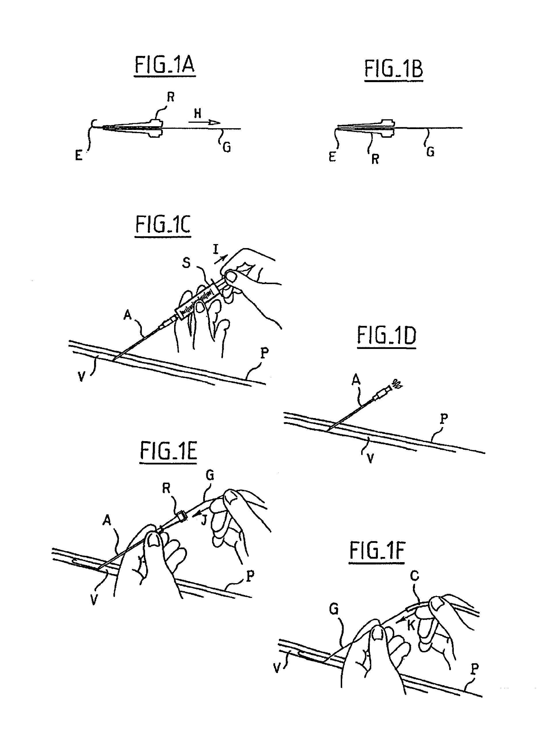
VYGON
View PDF8 Cites 58 Cited by
  • Summary
  • Abstract
  • Description
  • Claims
  • Application Information

AI Technical Summary

Benefits of technology

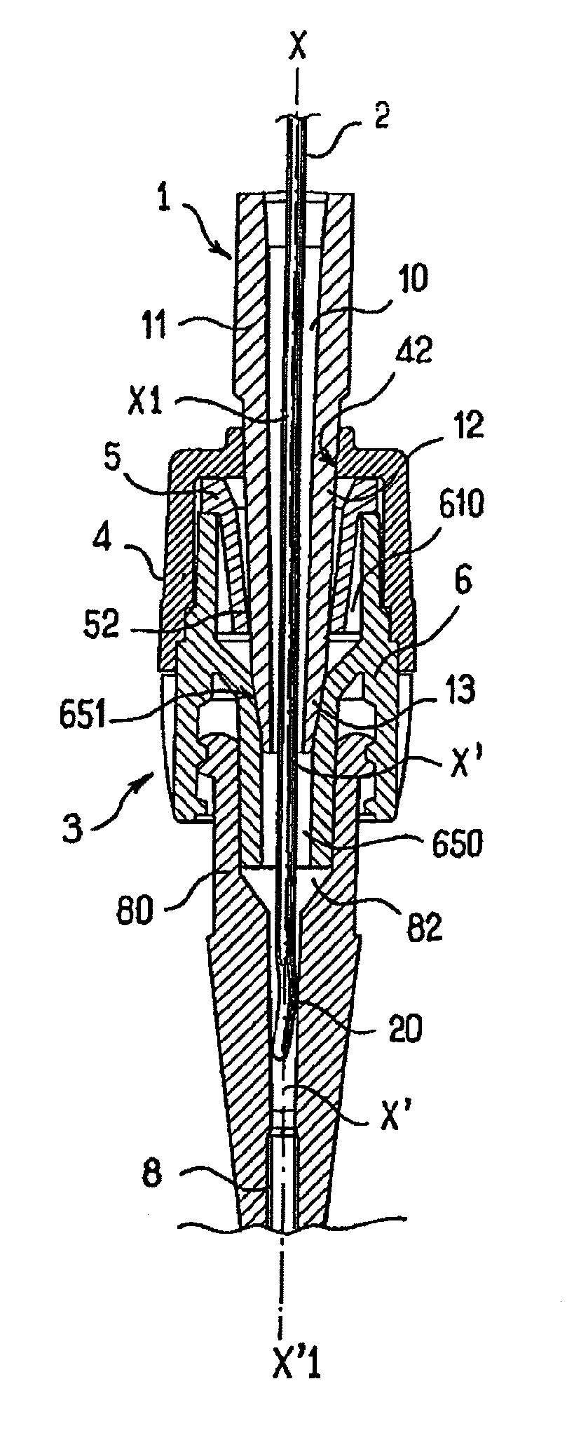
[0031]said straightener is pierced with an axial lumen, the diameter of which is sufficiently large for letting through the guide wire when its J-shaped end is deployed and sufficiently small for avoiding that this J-shaped end bends on itself and the outer surface of the distal end of the straightener has a shape and suitable dimensions for ensuring liquid-tight mating with said leaktight mating surface of the connector.

Problems solved by technology

This technique however has drawbacks in that it requires many manipulations and in that blood losses may be significant, notably when the syringe S is disconnected from the needle A, as this is illustrated in FIG. 1D.
However, taking into account the pressure prevailing inside arteries, blood losses may be much more significant before complete introduction of the guide wire G inside the artery.
However, these devices are complex, which make them more expensive to manufacture and more complicated to use.
Indeed, upon using one of these two systems, the practitioner is found pricking with bulky equipment: the needle plus the syringe plus the guide straightener plus the wound guide in a protective tube.
However, such a device has the drawback of not being perfectly sealed, since it is difficult to guarantee the perfect seal of a slit around a guide wire of cylindrical shape.

Method used


Image

  • Device for introducing a catheter guide wire into a vessel
  • Device for introducing a catheter guide wire into a vessel
  • Device for introducing a catheter guide wire into a vessel

Examples


Embodiment Construction

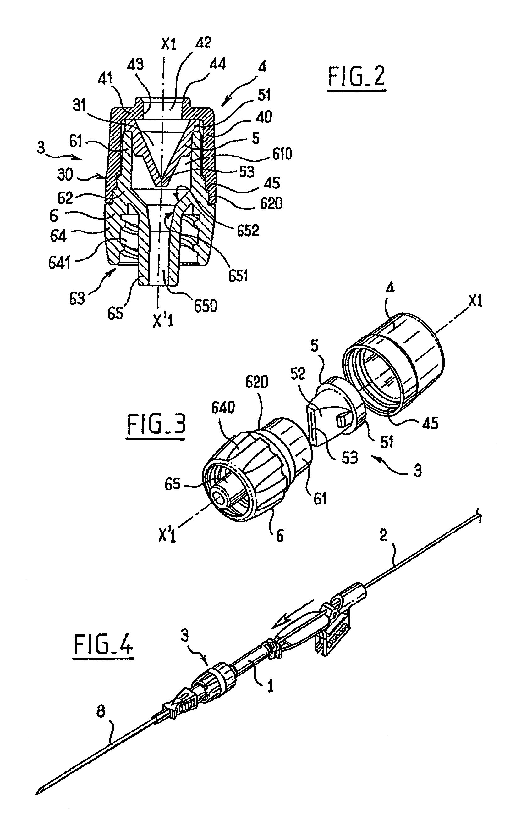
[0039]The device according to the invention is a pair consisting of a straightener 1 and a connector 3.

[0040]Referring to FIG. 6, it may be seen that the straightener 1 has a general elongated and tubular shape.

[0041]It is crossed right through by a lumen 10 which extends along its longitudinal axis X-X′.

[0042]The straightener includes three portions, i.e. a proximal end 11 with a larger diameter allowing it to be gripped by the practitioner, a conical distal opposite end 13 and a middle portion 12, the conicity of which is of a smaller slope than that of the distal end 13 and which extends between said ends 10 and 13.

[0043]The lumen 10 is also of a slightly conical shape, its diameter decreasing between the proximal end 11 and the distal end 13, in order to facilitate the introduction of a guide wire 2, such a wire being currently available commercially.

[0044]This guide wire 2 is a wire of flexible material, one of the ends 20 of which is in the natural condition bent on itself, wh...


PUM


Abstract

A device for introducing a catheter guide wire into a vessel of a patient has a connector and a straightener for a J-shaped end of the guide wire, the connector having an axial bore, and its distal end and proximal end permitting a connection of the Luer type to a needle and to a syringe, respectively. The connector supports, on its inside, a sealing valve equipped with a slit, and the axial bore has, in its portion between the sealing valve and the distal end of the connector, a leaktight mating surface, the shape of which is such that it permits liquid-tight mating with the outer surface of the distal end of the straightener, when the latter is introduced into the connector via the sealing valve.

Description

BACKGROUND OF THE INVENTION[0001]The invention is located in the field of medical instrumentation; more specifically catheters intended to be introduced into the blood of lymph stream of patients.[0002]The present invention relates to a device for introducing a flexible guide wire, with a J-shaped end, inside the circulatory system of a patient, this guide wire subsequently allowing placement of a catheter.[0003]Central venous catheters may be introduced into the veins by sliding around a spiral and flexible guide, the latter having been introduced therein beforehand by means of a needle.[0004]This technique is known to one skilled in the art under the name of the “Seldinger technique”. It will now be briefly described with reference to the enclosed FIGS. 1A-1F I which are diagrams illustrating the main steps.[0005]Referring to FIG. 1A, it may be seen that when a practitioner wants to insert a catheter into a vein, the walls of which are rather thin, to do this he / she uses a flexibl...

Claims


Application Information

Patent Timeline
IPC IPC(8): A61B5/00A61M25/00A61M25/16
CPCA61M25/09041A61M39/0606A61M39/045A61M2039/0633A61M2039/062A61M2039/0646
Inventor CARREZ, JEAN-LUCDALLE, VALERYGUYOMARC'H, PIERRICK
Owner VYGON
Learn More