Fan and motor thereof

a technology of a fan and a motor, which is applied in the direction of magnetic circuit rotating parts, piston pumps, magnetic circuit shapes/forms/construction, etc., can solve the problems of high manufacturing cost, reduce the occupied area of the stator, increase the disposable area of the blades, and improve the use efficiency of the fram

Active Publication Date: 2012-08-28
DELTA ELECTRONICS INC
View PDF7 Cites 1 Cited by
  • Summary
  • Abstract
  • Description
  • Claims
  • Application Information

AI Technical Summary

Benefits of technology

[0007]In view of the foregoing, the purpose of the present invention is to provide a fan and a motor thereof that increase the disposable area for the blades of the fan by changing the designs of blades and motor structure, thereby improving the heat dissipation efficiency, simplifying the winding method of the stator, and thus decreasing the manufacturing costs.
[0010]As mentioned above, the fan and motor thereof according to the present invention have the following features. The winding is disposed at the inner side or the outer side of the stator core. The first magnetic conducting sheet and the second magnetic conducting sheet are disposed at two sides of the stator core, respectively. The projections of the magnetic poles of the first and second magnetic conducting sheets alternate with each other. Moreover, the rotor magnetic ring and the blades can be formed by injection molding and are disposed in the stator core, so as to form an inner-rotor motor to drive the fan to rotate. Compared with the prior art, the present invention changes the positions of magnetic poles and winding method of the stator, so that the magnetic poles of the stator are disposed at different planes, respectively, and the projections of the magnetic poles alternate with each other. So as to increase the disposable area for the blades and decrease the occupied area of the stator, and make the space of the frame be used efficiently. In addition, the winding method for the windings is simplified, the winding time is decreased, so as to decrease the assembly time and the manufacturing cost.

Problems solved by technology

In addition, the windings 13 must be wound on the silicon steel sheets 12 respectively, so that the manufacturing costs are high.

Method used


Image

  • Fan and motor thereof
  • Fan and motor thereof
  • Fan and motor thereof

Examples


Embodiment Construction

[0016]The present invention will be apparent from the following detailed description, which proceeds with reference to the accompanying drawings, wherein the same references relate to the same elements.

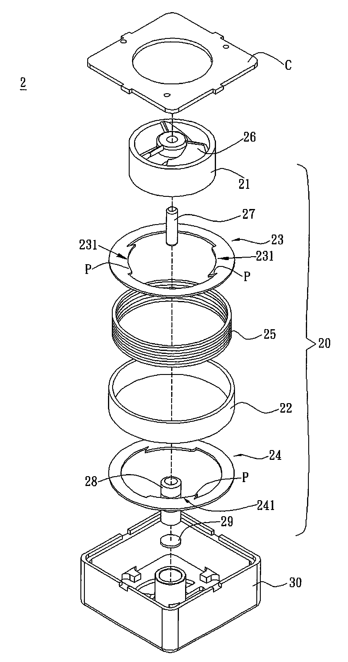
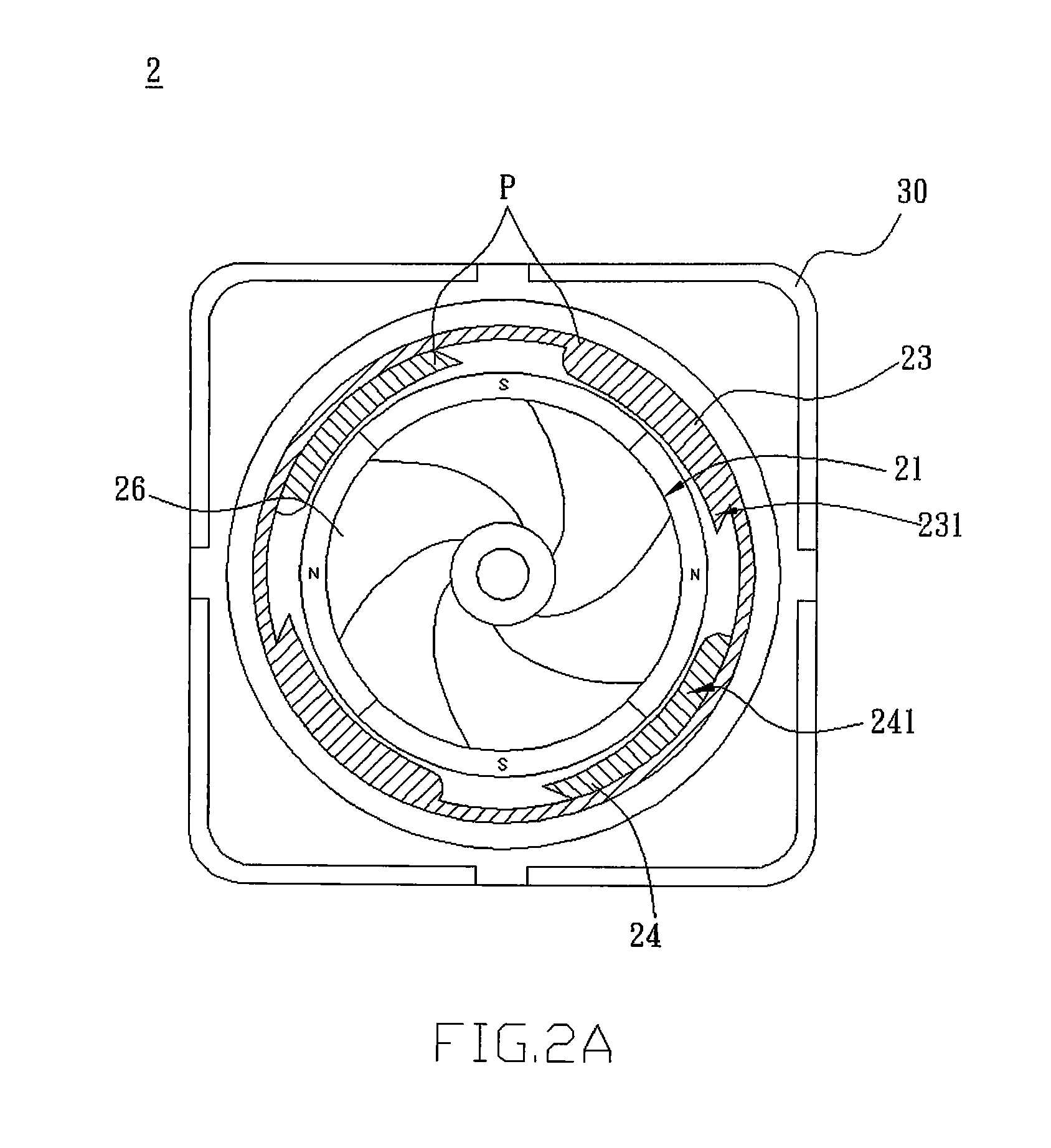
[0017]Referring to FIGS. 2A and 2B, a fan 2 according to an embodiment of the present invention includes a frame 30, a motor 20 and a plurality of blades 26. The motor 20 is an inner rotor motor and disposed in the frame 30. The motor 20 includes a rotor magnetic ring 21, a stator core 22, a first magnetic conducting sheet 23, a second magnetic conducting sheet 24 and a winding 25. In practice, the first magnetic conducting sheet 23 or the second magnetic conducting sheet 24 can be a silicon steel sheet. The stator of the motor 20 is constructed from the stator core 22, the first magnetic conducting sheet 23, the second magnetic conducting sheet 24 and the winding 25.

[0018]Referring to FIG. 2B and FIG. 3, the stator core 22 is a magnetic conducting yoke and comprises iron, and the sta...


PUM


Abstract

A motor includes a rotor magnetic ring, a stator core, a first magnetic conducting sheet and a second magnetic conducting sheet. The stator core is disposed around and out of the rotor magnetic ring. The first magnetic conducting sheet has a ring shape with a protruding portion serving as a first magnetic pole. The second magnetic conducting sheet has a ring shape with a protruding portion serving as a second magnetic pole. The first magnetic conducting sheet is disposed at the upper side of the stator core, and the second magnetic conducting sheet is disposed at the lower side of the stator core. The projections of the first and second magnetic poles alternate with each other. A fan including the motor is also disclosed.

Description

CROSS REFERENCE TO RELATED APPLICATIONS[0001]This Non-provisional application claims priority under 35 U.S.C. §119(a) on Patent Application No(s). 096150237, filed in Taiwan, Republic of China on Dec. 26, 2007, the entire contents of which are hereby incorporated by reference.BACKGROUND OF THE INVENTION[0002]1. Field of Invention[0003]The present invention relates to a fan and a motor thereof, and in particular to a fan and an inner-rotor motor thereof.[0004]2. Related Art[0005]In the trend of miniaturizing current fan applied to electronic apparatus or system, it is necessary to enhance the heat dissipation efficiency of the fan within the limited volume. To achieve this goal, it is an applicable way to adjust the size of the blade of the fan.[0006]Generally speaking, according to the dispositions of the rotor and stator, the motor of the fan is divided into an outer-rotor motor and an inner-rotor motor. Referring to FIG. 1, a conventional fan 1 includes an inner-rotor motor 10 for...

Claims


Application Information

Patent Timeline
Patent Type & Authority Patents(United States)
IPC IPC(8): F04D25/06H02K1/14H02K1/27
CPCH02K1/145H02K1/278H02K7/14H02K21/145F04D25/0606
Inventor TSAI, SHUI-FALIANG, HUNG-YICHEN, HOU-CHUHSU, CHIN-CHU
Owner DELTA ELECTRONICS INC
Why Eureka
Try Eureka