
Communication control method, communication system, communication control apparatus and wireless base station

a communication control and wireless technology, applied in the field of communication control methods, communication systems, communication control apparatuses and wireless base stations, can solve problems such as failure of handover communication interference regions, and difficulty in assigning different frequency bands to neighboring wireless base stations in the wireless communication system, and achieve the effect of stable communication and stable communication

Active Publication Date: 2012-08-14
KYOCERA CORP
View PDF15 Cites 1 Cited by
  • Summary
  • Abstract
  • Description
  • Claims
  • Application Information

AI Technical Summary

Benefits of technology

The patent text describes a problem where a terminal may communicate with multiple wireless base stations simultaneously, but it cannot use a technique called site diversity to improve transmission quality. The technical effect of this patent is to provide a communication control method, system, and apparatus that can achieve stable communication without interference from neighboring wireless base stations and quickly handover to a neighboring base station for a smooth transition.

Problems solved by technology

However, it is assumed that, in light of an effective usage of limited frequencies, unlike the cellular system, it is difficult to assign different frequency bands to the neighboring wireless base stations in a wireless communication system such as WiMAX which uses wide frequency band.
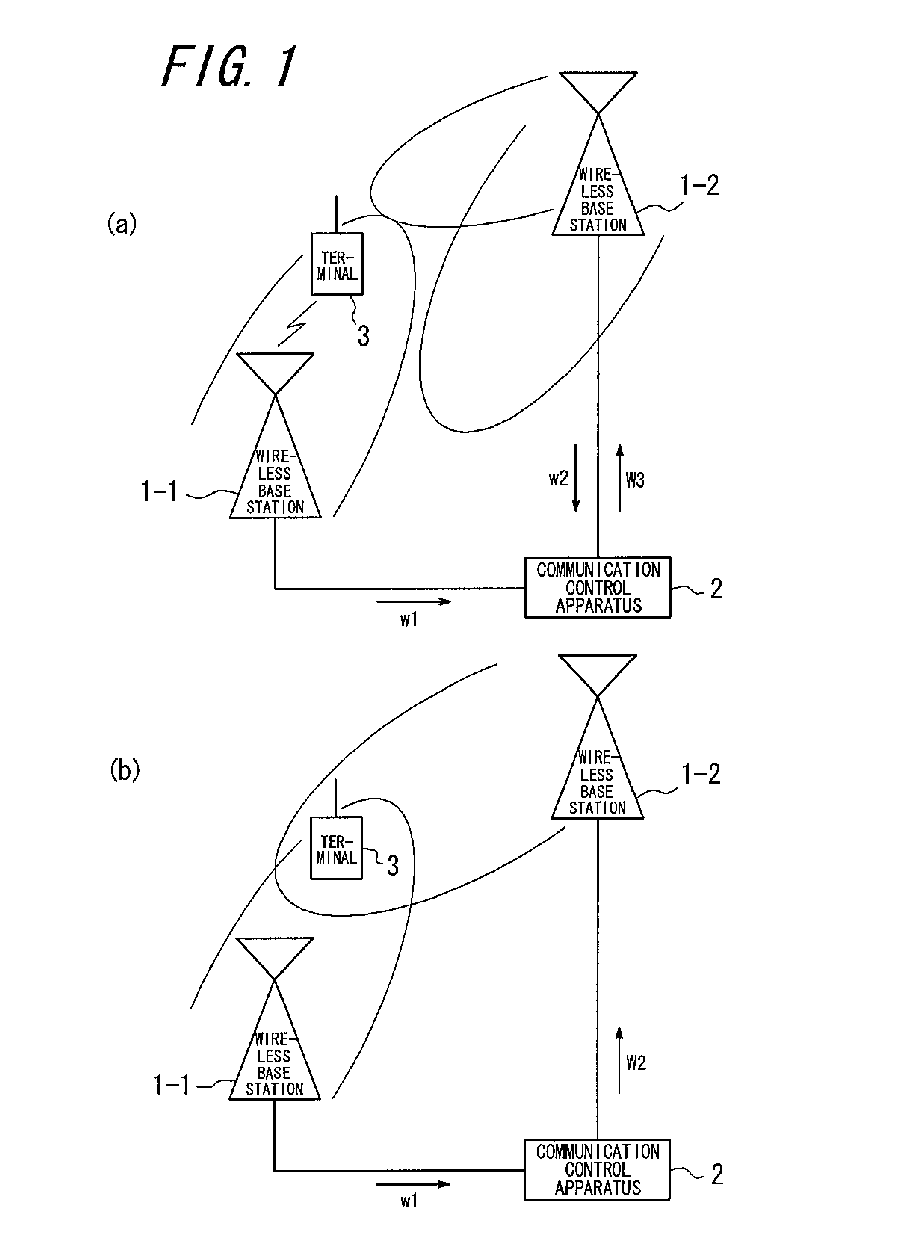
For that reason, using the same frequency band at neighboring wireless base stations generates a communication interference region therebetween because of the synchronization of frames between the wireless base stations.
When the communication interference region is generated, since a terminal in the region simultaneously receives radio waves transmitted from neighboring wireless base stations, there is a concern about difficulty to separate the radio waves transmitted from one another in a region where reception intensities of the transmitted radio waves are at approximately the same level, which leads to a failure of handover to the neighboring wireless base station and disconnection.

Method used


Image

  • Communication control method, communication system, communication control apparatus and wireless base station
  • Communication control method, communication system, communication control apparatus and wireless base station
  • Communication control method, communication system, communication control apparatus and wireless base station

Examples


first embodiment

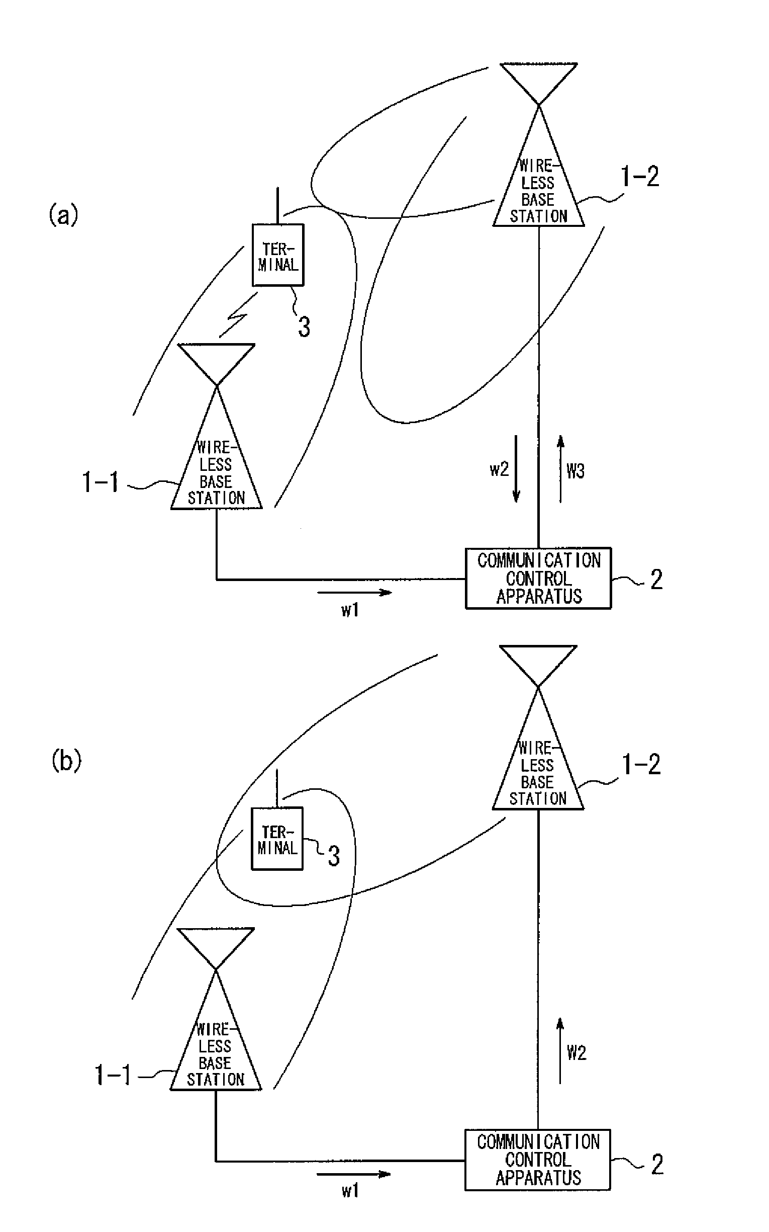
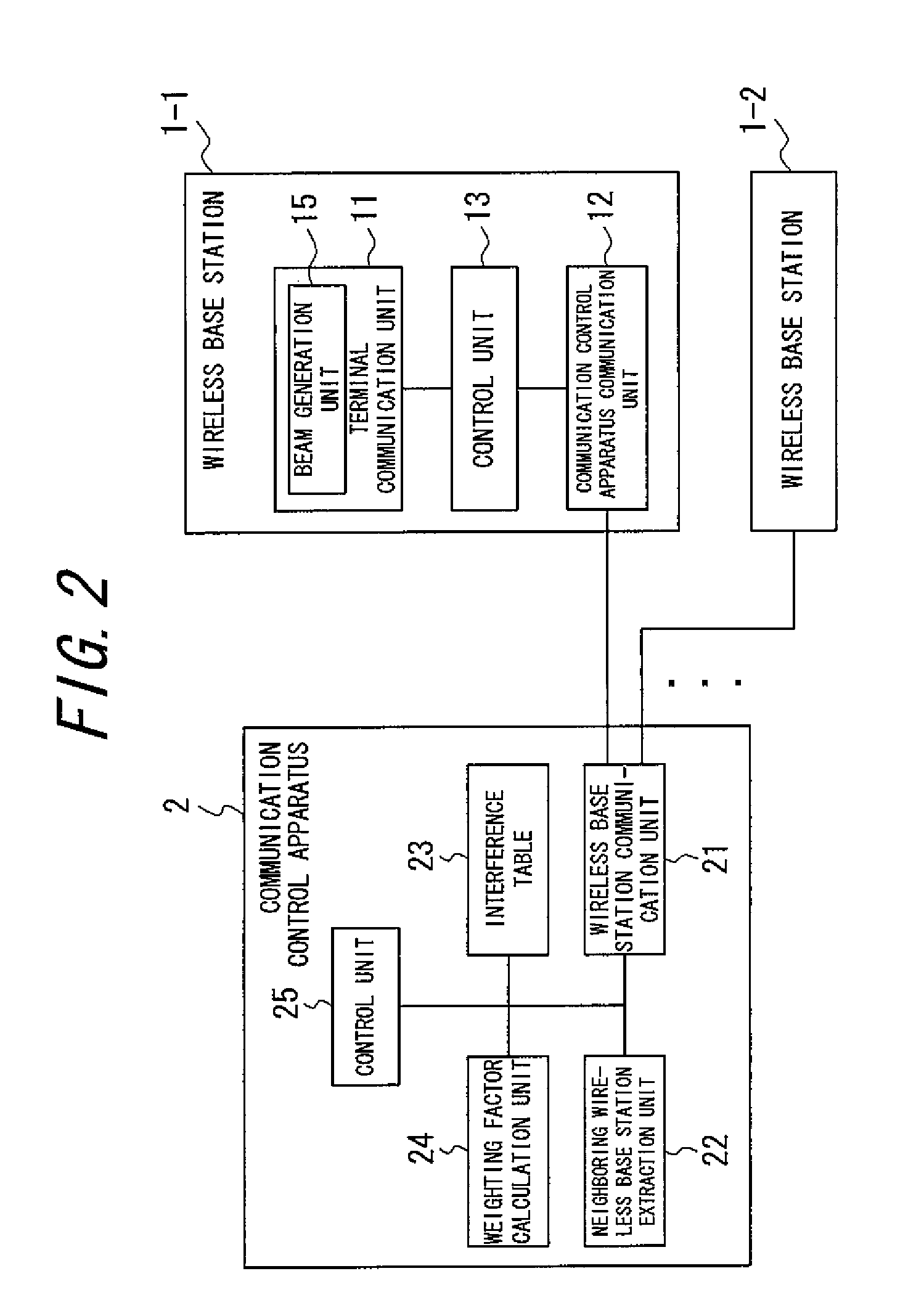
[0116]FIG. 1 is a diagram illustrating a principle of a communication system according to a first embodiment of the present invention. The communication system shown in FIG. 1 is provided with a plurality of wireless base stations 1-1, 1-2, . . . and a communication control apparatus 2 for controlling the plurality of wireless base stations. Each of the wireless base stations 1-1, 1-2, . . . (hereinafter referred to as a wireless base station 1 as well when indicating a single wireless base station) is capable of wirelessly communicating with a terminal (wireless communication apparatus) 3 located in a communication area of the wireless base station 1 by use of the same frequency band and TDD with frame synchronization between the wireless base stations. In addition, each wireless base station 1 has a plurality of antennas and adopts an adaptive array antenna to improve a link state by controlling directionality of the antenna to the terminal 3 communicating therewith. The terminal ...

second embodiment

[0160]FIG. 8 is a diagram illustrating a principle of a communication system according to a second embodiment of the present invention. The communication system shown in FIG. 8 is provided with a plurality of wireless base stations 101-1, 101-2, . . . and a communication control unit 102 for controlling the plurality of wireless base stations. Each of the wireless base stations 101-1, 101-2, . . . (hereinafter referred to as a wireless base station 101 when indicating a single wireless base station) is capable of wirelessly communicating with a terminal (wireless communication apparatus) 103 in a communication area of the wireless base station 101 by use of the same frequency band and TDD with frame synchronization between the wireless base stations. In addition, each wireless base station 101 has a plurality of antennas and adopts an adaptive array antenna to improve a link state by controlling directionality of the antenna to the terminal 103 communication therewith.

[0161]In the c...


PUM


Abstract

A communication control method for a communication system stores location information indicating an interference region by neighboring wireless base stations, a first weighting factor for one wireless base station to direct its beam to the interference region, and a second weighting factor for the other wireless base station to direct its beam, correspondingly to one another in an interference table The system judges whether a terminal is located in the interference region by obtaining weighting factors adopted by each of the neighboring wireless base stations while the one wireless base station communicates with the terminal, compares the weighting factors to the first and second weighting factors stored in the interference table, and controls beam generation of the other wireless base station to prevent its interference when the terminal is located in the interference region.

Description

CROSS REFERENCE TO RELATED APPLICATION[0001]This application is a national stage of international application No. PCT / JP2008 / 055581 filed on Mar. 25, 2008, which also claims priority to and the benefit of Japanese Patent Application No. 2007-89084 filed Mar. 29, 2007 and Japanese Patent Application No. 2007-89102 filed on Mar. 29, 2007, the entire contents of those are incorporated herein by reference.TECHNICAL FIELD[0002]The present invention relates to a communication control method, a communication system, a communication control apparatus and a wireless base station.BACKGROUND ART[0003]A cellular system is conventionally known as a mobile communication system. In addition, a standardization of high-speed wireless communication such as WiMAX (Worldwide Interoperability for Microwave Access), for example, has been recently promoted.[0004]The cellular system prevents radio waves from neighboring wireless base stations from interfering with one another by use of different frequency ...

Claims


Application Information

Patent Timeline
Patent Type & Authority Patents(United States)
IPC IPC(8): H04W4/00H04W72/04
CPCH04B7/0617H04W72/082H04W72/046H04W72/541
Inventor YAMAZAKI, CHIHARUMORITA, KUGO
Owner KYOCERA CORP
Learn More