High fidelity simulation of synthetic aperture radar

a synthetic aperture radar and simulation technology, applied in the field of synthetic aperture radar simulations, can solve the problems of reducing the accuracy of synthetic aperture radar, rendering simulation unrealistic, and integrating such data and rasterizing vector-based data requires significant processing power, so as to achieve less processing and simplify quality control. the effect of time and less processing

Active Publication Date: 2012-08-14
LOCKHEED MARTIN ACTING BY & THROUGH SIMULATION TRAINING & SUPPORT
View PDF10 Cites 13 Cited by
  • Summary
  • Abstract
  • Description
  • Claims
  • Application Information

AI Technical Summary

Benefits of technology

[0007]A database compiler inputs the channel data and generates a rasterized runtime database used to depict the SAR map during the SAR simulation. The rasterized runtime database is typically in a proprietary format unique to a particular Digital Radar Landmass Simulator (DRLMS) manufacturer. Because the IFF is raster-based, and the channel data is raster data, no polygon-to-raster conversion is required, and the database compiler can generate the rasterized runtime database using substantially less processing, and in substantially less time, than is required to generate a rasterized runtime database from vector data. Moreover, the use of raster data simplifies quality control by enabling the channel data to be examined by standard geographic information system (GIS) software packages.

Problems solved by technology

Unfortunately, 3D polygonal development of high density urban areas is time intensive and costly.
Moreover, because of the cost associated with manual 3D polygonal development, many of the ancillary features, such as cars, rocks, and bushes, are simulated using available ground imagery.
While ground imagery may be acceptable for lower resolution radar simulations, in a high-fidelity SAR map simulation such ancillary features will appear flat, rendering the simulation unrealistic.
Integrating such data and rasterizing vector-based data requires significant processing power and may take a substantial amount of time.
Moreover, the use of different formats and different input sources makes it difficult to ensure quality control of the final runtime database.

Method used


Image

  • High fidelity simulation of synthetic aperture radar
  • High fidelity simulation of synthetic aperture radar
  • High fidelity simulation of synthetic aperture radar

Examples


Embodiment Construction

[0024]The embodiments set forth below represent the necessary information to enable those skilled in the art to practice the invention and illustrate the best mode of practicing the invention. Upon reading the following description in light of the accompanying drawing figures, those skilled in the art will understand the concepts of the invention and will recognize applications of these concepts not particularly addressed herein. It should be understood that these concepts and applications fall within the scope of the disclosure and the accompanying claims.

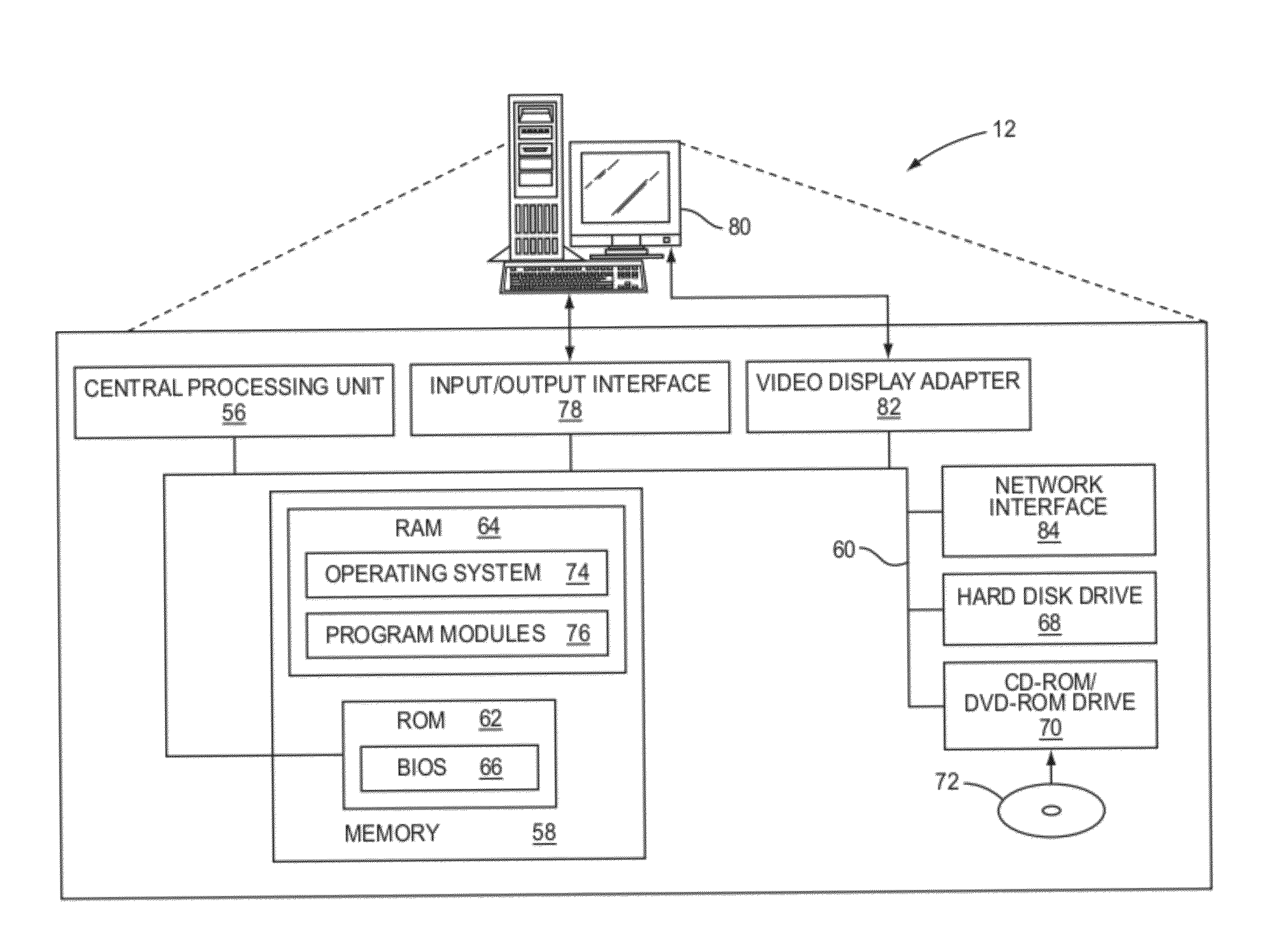
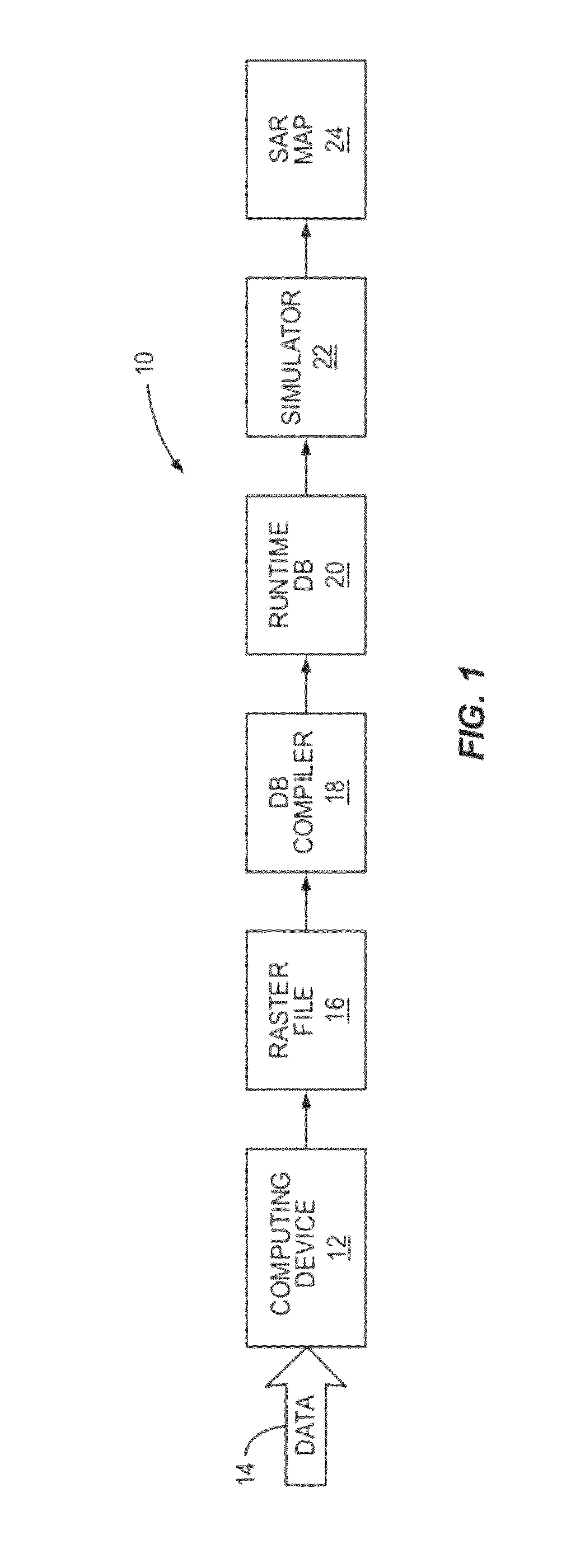
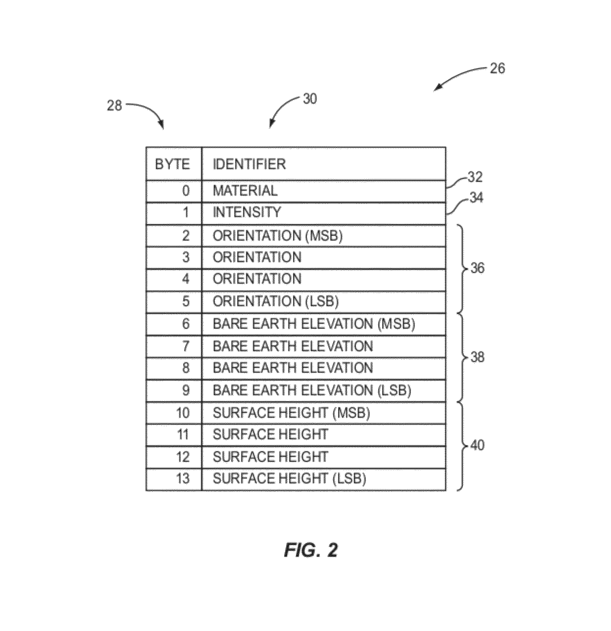
[0025]The present invention relates to a raster-based interchange file format (IFF) that defines synthetic aperture radar (SAR) scenery in a format that may be used by any database compiler, or formatter, to generate a runtime database of a SAR map for a simulator. The IFF may be implemented in a data structure in a memory, in a file, or in any other suitable electronic medium. The raster-based IFF reduces the processing time of t...


PUM


Abstract

Methods and systems for generating a raster file in a raster file format for use in a Digital Radar Landmass Simulator (DRLMS). A file in the raster file format defines synthetic aperture radar (SAR) scenery for use in generating a runtime database. The raster file contains a plurality of texture elements (texels) that define the SAR scenery. Each texel may have a material identifier, which identifies a material composition of a respective surface region of the SAR scenery; a surface height identifier, which identifies a surface height with respect to a bare earth elevation (BEE) value of the respective surface region; and a BEE identifier, which identifies a BEE of the respective surface region. A method for determining surface height identifiers based on digital surface model (DSM) elevation data is also provided.

Description

FIELD OF THE INVENTION[0001]The present invention relates to synthetic aperture radar (SAR) simulations, and in particular to a raster file format for use in a SAR simulation.BACKGROUND OF THE INVENTION[0002]Simulators are used extensively by the military to train fighter pilots. It is important that a simulator provide as realistic an experience as possible. A fighter jet simulator concurrently simulates many aspects of a flight, such as an out-the-window (OTW) simulation simulating what a pilot sees out the cockpit window while flying the fighter jet, and a radar simulation simulating what a pilot sees when looking at a radar display.[0003]Some current generation fighter jets include a synthetic aperture radar (SAR) which provides a pilot with a high-resolution SAR map of potential targets on the ground. SAR is typically simulated using a Digital Radar Landmass Simulator (DRLMS). A SAR map includes terrain, lineal features such as roads and railroad tracks, and three-dimensional (...

Claims


Application Information

Patent Timeline
IPC IPC(8): G01S13/90G09B9/54G09B9/00G01S13/00
CPCG01S13/9035G01S17/89G09B9/54G01S13/9027
Inventor BURKY, JOHNSHAHAN, SHARON
Owner LOCKHEED MARTIN ACTING BY & THROUGH SIMULATION TRAINING & SUPPORT
Why Eureka
Try Eureka