Transformer, switching power supply device, and DC-DC converter device
a transformer and switching power supply technology, applied in the field of transformers, can solve the problems of increasing reducing the audible frequency of transformers, and small operation sound, so as to reduce the possibility of core breaking and reduce the possibility of transformer growl nois
- Summary
- Abstract
- Description
- Claims
- Application Information
AI Technical Summary
Benefits of technology
Problems solved by technology
Method used
Image
Examples
first embodiment
[0037]A first embodiment is described below.
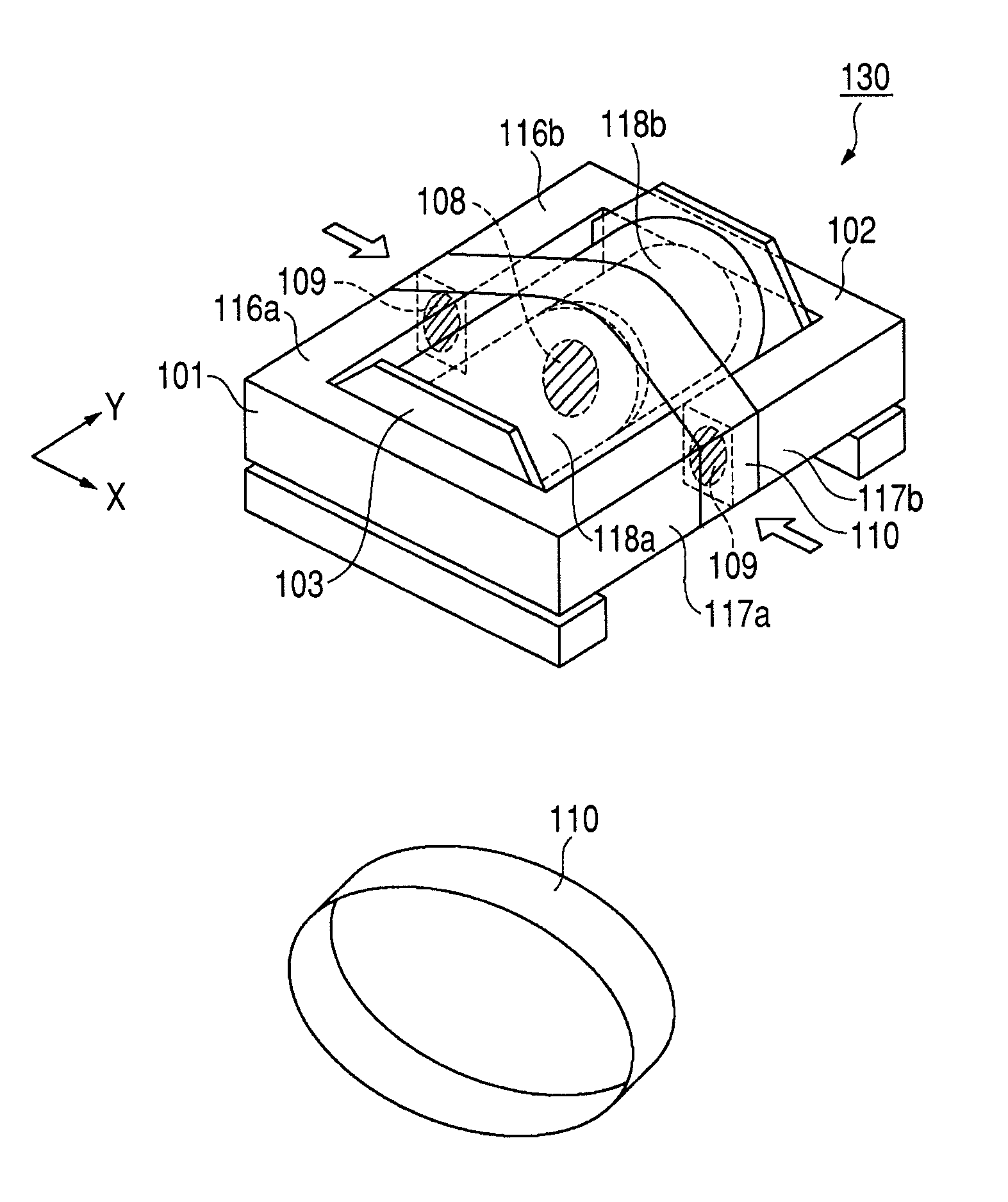
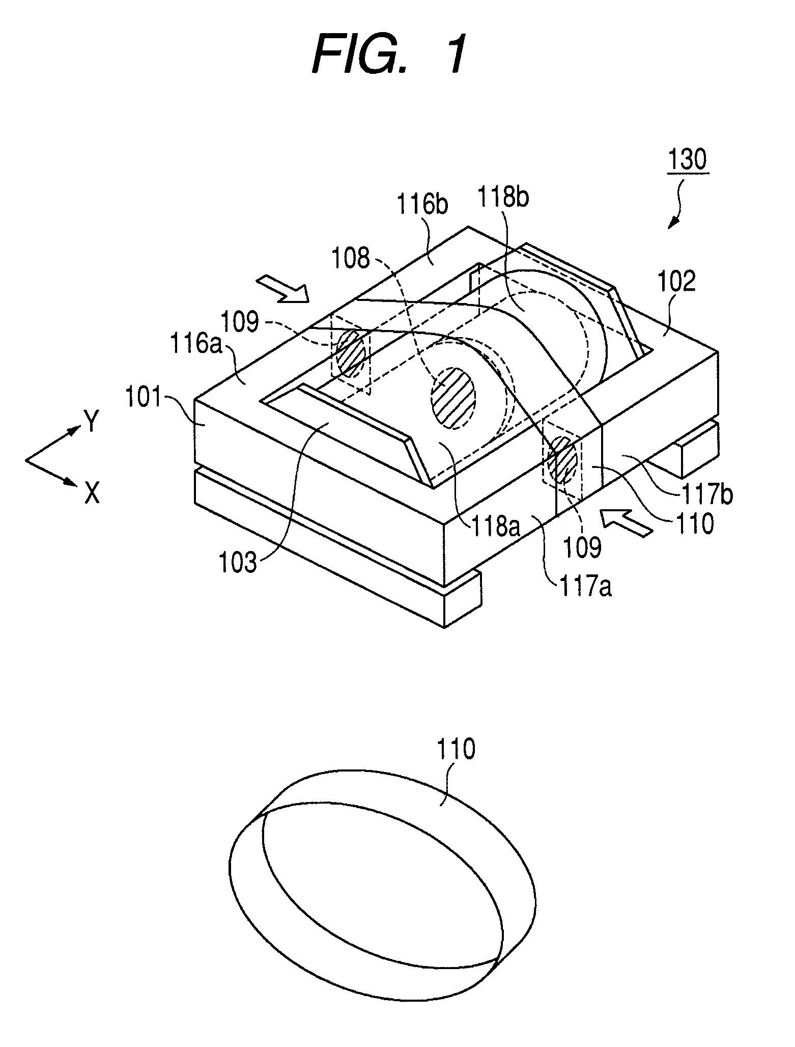
[0038]FIG. 1 is a perspective view illustrating an EE type transformer 130 according to the first embodiment. For example, the transformer 130 is used in a switching power supply device, a DC-DC converter device, and the like. A first ferrite core 101 shaped like the letter E in horizontal section includes a first magnetic outer leg 116a, a second magnetic outer leg 117a, and a magnetic center leg 118a. Likewise, a second ferrite core 102 includes a first magnetic outer leg 116b, a second magnetic outer leg 117b, and a magnetic center leg 118b. The first ferrite core 101 is an example of a first core, and the second ferrite core 102 is an example of a second core.
[0039]A coil bobbin 103 has a primary coil and a secondary coil wound thereon. A shaft of the coil bobbin 103 is hollow, and the magnetic center legs 118a and 118b are inserted through this hollow shaft. A horizontal direction is a direction parallel to a horizontal plane that con...
second embodiment
[0055]The following describes a
[0056]In the first embodiment, the heat shrinkable tube 110 is used as the elastic member that applies pressure to the magnetic outer legs of the first ferrite core 101 and the magnetic outer legs of the second ferrite core 102. In the second embodiment, a flexible tube is used as the elastic member. The heat shrinkable tube 110 shrinks when heated. On the other hand, the flexible tube does not need such a heating step, and therefore the manufacturing process can be simplified.
[0057]FIG. 4 is a perspective view illustrating an EE type transformer 400 according to the second embodiment. A flexible tube 410 is adopted instead of the heat shrinkable tube 110. As the flexible tube 410, a tube made from a material having an excellent high temperature resistance, heat cycle resistance, tear resistance, and fire retardance, such as silicon rubber, can be used.
[0058]According to the second embodiment, the effect of simplifying the manufacturing process can be ...
third embodiment
[0059]The following describes a
[0060]As the elastic member that applies pressure to the magnetic outer legs of the first ferrite core 101 and the magnetic outer legs of the second ferrite core 102, the heat shrinkable tube 110 is adopted in the first embodiment and the flexible tube 410 is adopted in the second embodiment. In the third embodiment, a springing member is adopted.
[0061]FIG. 5 is a perspective view illustrating an EE type transformer 500 according to the third embodiment. In this embodiment, a springing member 510 is adopted instead of the heat shrinkable tube 110 or the flexible tube 410. The springing member 510 applies pressure to the magnetic outer legs of the first ferrite core 101 and the magnetic outer legs of the second ferrite core 102, in the direction from the magnetic outer legs toward the magnetic center legs. This enables an interfacial pressure to act upon the abutting surfaces of the magnetic outer legs.
[0062]According to the third embodiment, the same e...
PUM
| Property | Measurement | Unit |
|---|---|---|
| magnetic | aaaaa | aaaaa |
| magnetic center | aaaaa | aaaaa |
| pressure | aaaaa | aaaaa |
Abstract
Description
Claims
Application Information
 - R&D
- Intellectual Property
- Life Sciences
- Materials
- Tech Scout
- Unparalleled Data Quality
- Higher Quality Content
- 60% Fewer Hallucinations
Browse by: Latest US Patents, China's latest patents, Technical Efficacy Thesaurus, Application Domain, Technology Topic, Popular Technical Reports.
© 2025 PatSnap. All rights reserved.Legal|Privacy policy|Modern Slavery Act Transparency Statement|Sitemap|About US| Contact US: help@patsnap.com


