
Head drive apparatus of inkjet printer and inkjet printer

a technology of inkjet printer and head drive device, which is applied in the direction of dc amplifiers, amplifiers with modulator-demodulator, semiconductor devices/discharge tubes, etc., can solve the problems of inefficiency of linear drive itself of transistors, amplifiers with drawbacks of large circuit sizes, and long printing tim

Inactive Publication Date: 2012-08-14
SEIKO EPSON CORP
View PDF131 Cites 8 Cited by
  • Summary
  • Abstract
  • Description
  • Claims
  • Application Information

AI Technical Summary

Benefits of technology

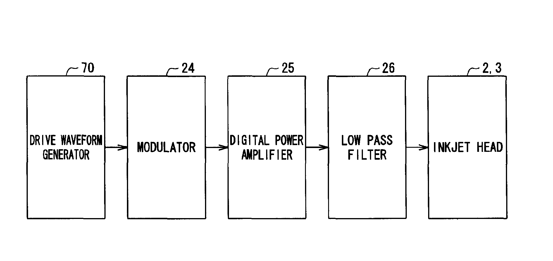
The present invention provides a head drive apparatus for an inkjet printer that can rapidly rise and fall a drive signal to actuators without requiring a cooling unit. The apparatus includes a drive unit that applies a drive signal to actuators, a drive waveform generator that generates a drive waveform signal, a modulator that pulse modulates the drive waveform signal, a digital power amplifier that amplifies the modulated signal, a low pass filter that smooths the amplified signal, and a frequency characteristics adjusting unit that adjusts the filter's frequency characteristics as a function of the number of actuators. The apparatus can make the drive signals actually applied to actuators constant, regardless of the number of actuators. The invention also provides a method for adjusting the filter's frequency characteristics to remove only certain components or components within a predetermined range.

Problems solved by technology

Therefore, it has a drawback in that it takes a longer time for printing than a print apparatus in another scheme, for example, a laser printer or a copying machine using electrographic technique.
However, in a current amplifier with such configuration, a linear drive itself of a transistor is inefficient.
Moreover, such an amplifier has a drawback of a large circuit size since the transistor itself should be large for a countermeasure against heat, and the transistor needs a cooling plate radiator.
Particularly, the largeness of the cooling plate radiator is a major obstacle to the layout.
As such, the head drive apparatus of an inkjet printer using the DC / DC converter in JP-A-2005-035062 has a problem in that a waveform, for example, rapid rise and fall of a drive signal cannot be gained necessary for an inkjet head to jet ink drops well.
Of course, the head drive apparatus of an inkjet printer in which a pair of transistors in push-pull connection amplifies current of an actuator drive signal in JP-A-2004-306434 has a problem in that a cooling plate radiator is so large that it cannot be actually laid out particularly in a line head inkjet printer having a large number of nozzles, i.e., a large number of actuators.

Method used


Image

  • Head drive apparatus of inkjet printer and inkjet printer
  • Head drive apparatus of inkjet printer and inkjet printer
  • Head drive apparatus of inkjet printer and inkjet printer

Examples


Embodiment Construction

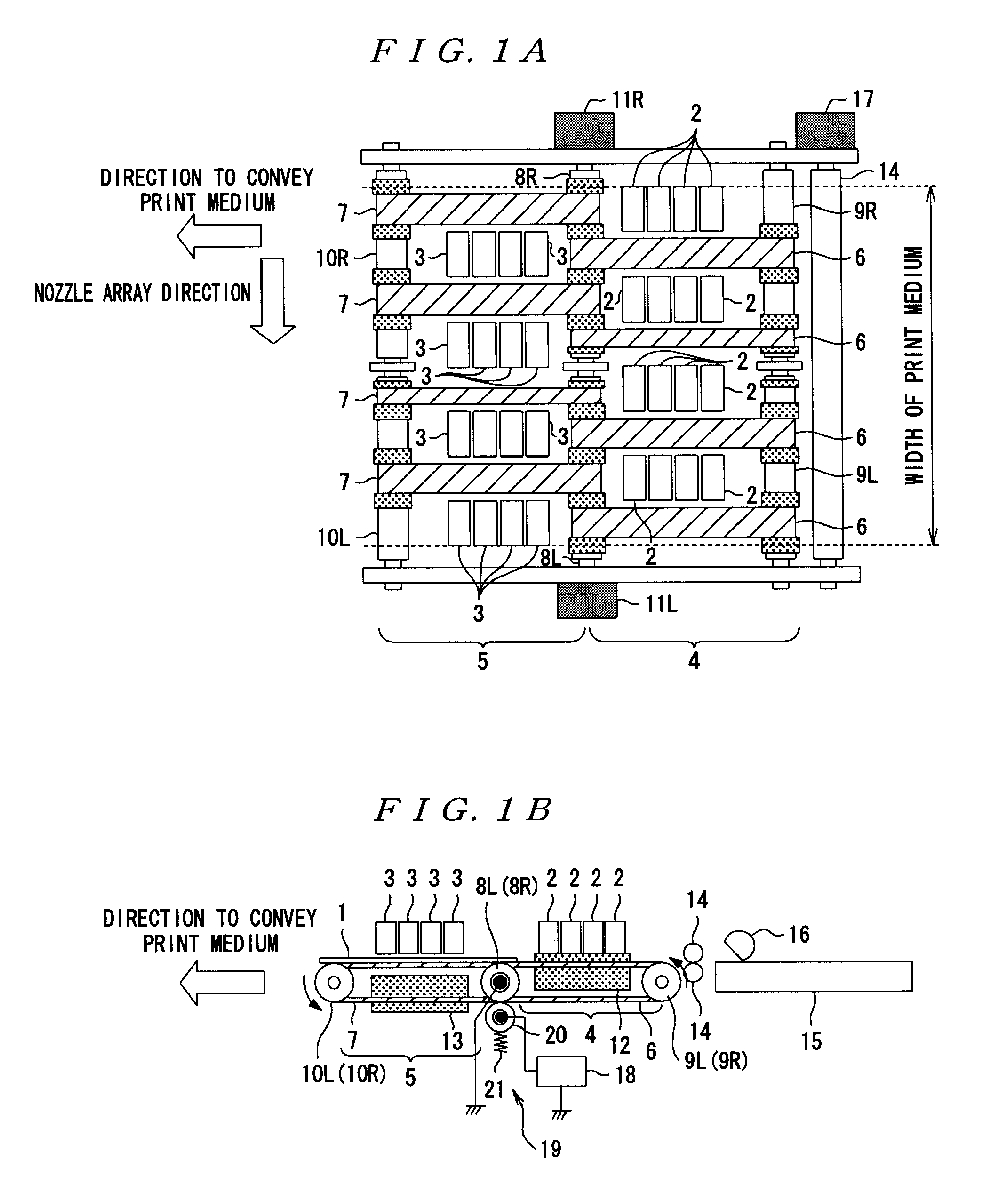
[0039]A first embodiment of an inkjet printer according to the present invention will be described with reference to the drawings.

[0040]FIGS. 1A and 1B are the overall configuration diagrams of an inkjet printer according to this embodiment: FIG. 1A is a top plain view of the printer; and FIG. 1B is a front view of the printer. In FIGS. 1A and 1B, a print medium 1 is a line head inkjet printer that is conveyed in a direction from the right to the left indicated by the arrow of the drawing and printed in a printing area on the way of the conveyor. However, the inkjet head according to the present embodiment is not arranged only at one place, but two inkjet heads are arranged at two places.

[0041]Reference numeral 2 in the drawing denotes a first inkjet head being provided on the upstream side of the direction in which the print medium 1 is conveyed, and reference numeral 3 denotes a second inkjet head being provided on the downstream side of the direction. A first conveyor unit 4 is p...


PUM


Abstract

A head drive device of an inkjet printer having a nozzles and corresponding actuators that jet liquid drops. A drive section that generates a drive signal to the actuators. The head drive device includes a drive waveform signal which is used as a reference of a signal to control drive of the actuators. A modulating section modulates a pulse of a drive waveform signal generated by the drive waveform generating system. A low pass filter smoothes a power-amplified modulated signal subjected to the power amplification by the digital power amplifier and supplies the signal as a drive signal to the actuators. A frequency characteristics adjusting section adjusts frequency characteristics of the low pass filter as a function of the number of the actuators.

Description

BACKGROUND[0001]1. Technical Field[0002]The present invention relates to an inkjet printer in which a plurality of nozzles jet minute ink drops of liquid ink of a plurality of colors and particles of the ink (ink dots) are formed on a print medium to draw pre-determined characters and images.[0003]2. Related Art[0004]An inkjet printer as in the above generally accomplishes low-cost and high-quality color printed material easily. As such, it is widely used not only in offices but also by general users along with popularization of a personal computer and a digital camera.[0005]Generally, in such an inkjet printer, a moving part called a carriage, for example, integrally comprising ink cartridges and print heads moves back and forth on a print medium in a direction crossing a direction to convey the medium, and nozzles of the print head jet (eject) liquid ink drops to form minute ink dots on the print medium. In this manner, pre-determined characters or images are drawn on the print me...

Claims


Application Information

Patent Timeline
Patent Type & Authority Patents(United States)
IPC IPC(8): B41J29/38H03F3/38
CPCB41J2/04541B41J2/04548B41J2/04568B41J2/04578B41J2/0458B41J2/04581B41J2/04588B41J2/04591B41J2/04595B41J2/04596
Inventor OSHIMA, ATSUSHITABATA, KUNIOSHINKAWA, OSAMUSUZUKI, TOSHIYUKIHATANO, TOMOKI
Owner SEIKO EPSON CORP
Learn More