
MEMS device with off-axis actuator

a technology of actuators and mems, applied in the field of microelectromechanical systems, can solve the problems of complicated mirror design, and achieve the effect of simplifying the design of the devi

Active Publication Date: 2012-08-07
ADVANCED NUMICRO SYST
View PDF4 Cites 4 Cited by
  • Summary
  • Abstract
  • Description
  • Claims
  • Application Information

AI Technical Summary

Benefits of technology

"The invention is a MEMS mirror device that has a mirror and a frame that can rotate around the mirror. The device also has a biaxial actuator that can rotate around the mirror and frame. This design allows the actuator to provide two axes of motion to the mirror, making it easier to design and operate."

Problems solved by technology

The result is a rather complicated design of the mirror and the frame that allows for rotation and electrical isolation of the voltages necessary to rotate the mirror about the first axis.

Method used


Image

  • MEMS device with off-axis actuator
  • MEMS device with off-axis actuator
  • MEMS device with off-axis actuator

Examples


Embodiment Construction

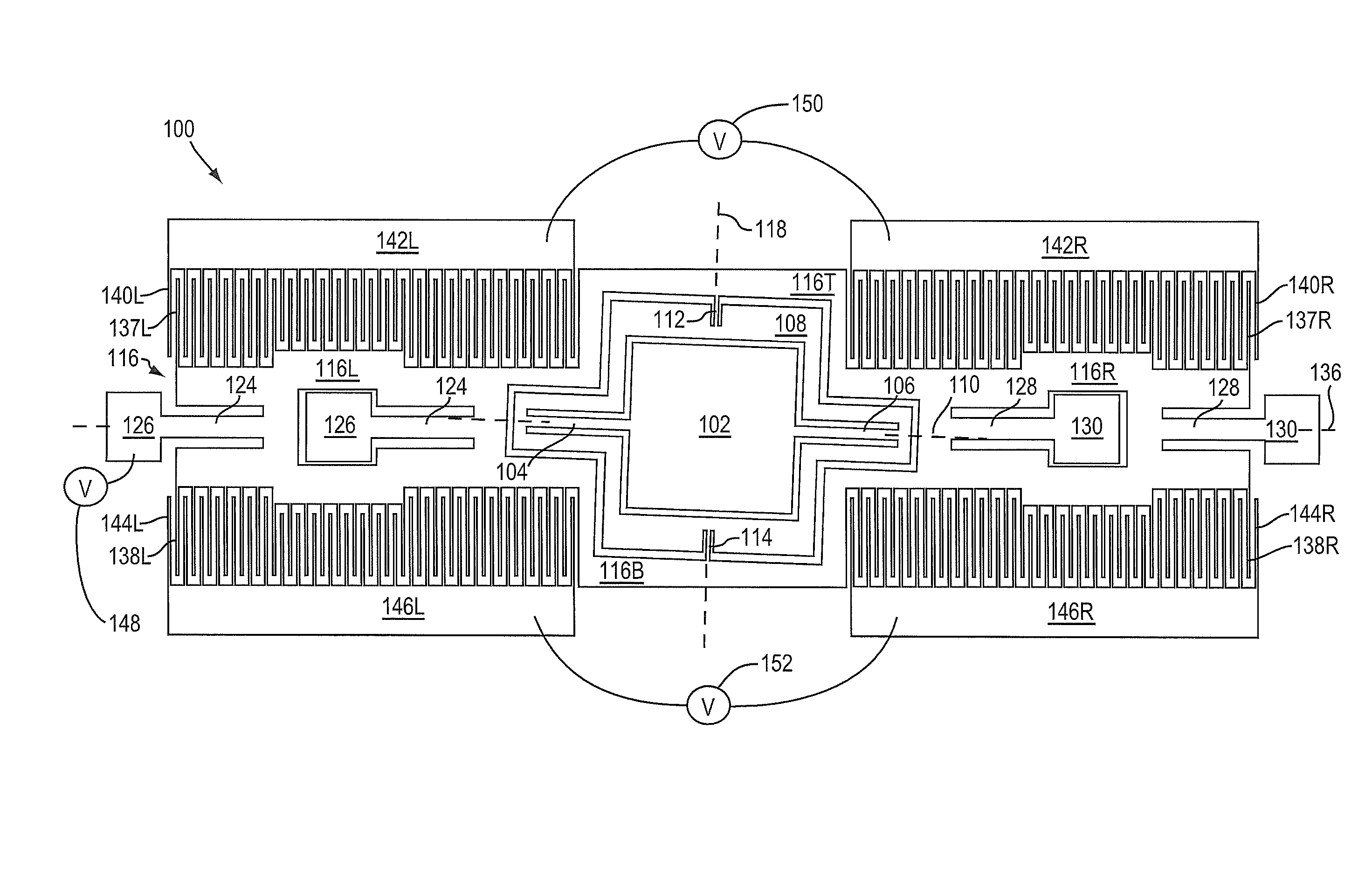
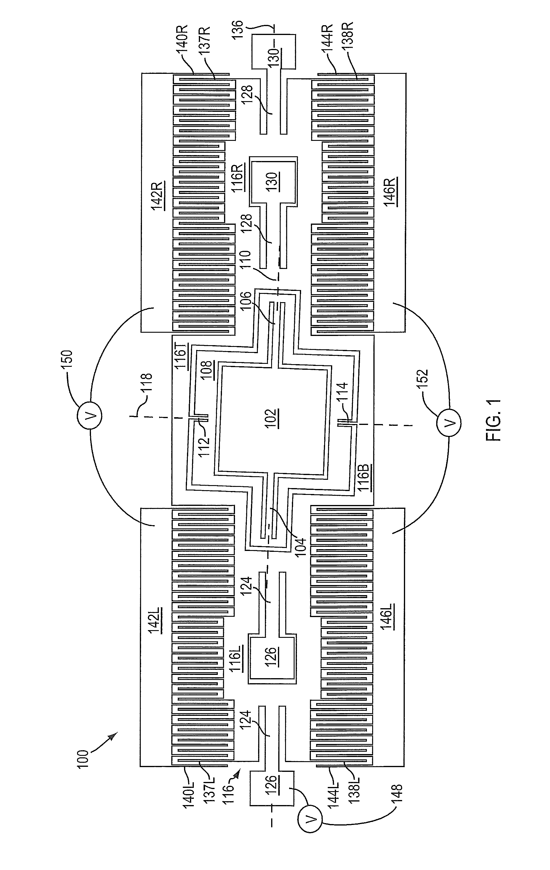
[0009]FIG. 1 illustrates a micro-electro-mechanical system (MEMS) mirror device 100 in one embodiment of the invention. Device 100 is typically made from a silicon substrate using conventional semiconductor processing methods (e.g., masking and etching). Device 100 can be used in any application that requires one or two axes of motion (e.g., a unidirectional or a bidirectional scanning mirror).

[0010]Device 100 includes a mirror 102 connected by springs 104 and 106 to a frame 108. The coupling between mirror 102 and springs 104 and 106 are located along a rotational axis 110 (hereafter mirror axis 110) so the mirror can rotate about the mirror axis relative to frame 108. In one embodiment, a rectangular mirror 102 is located within a rectangular frame 108, where the left and the right sides of the mirror are connected by springs 104 and 106 to the left and the right sections of the frame, respectively. Mirror 102 and frame 108 may have other shapes in other embodiments. Note that any...


PUM


Abstract

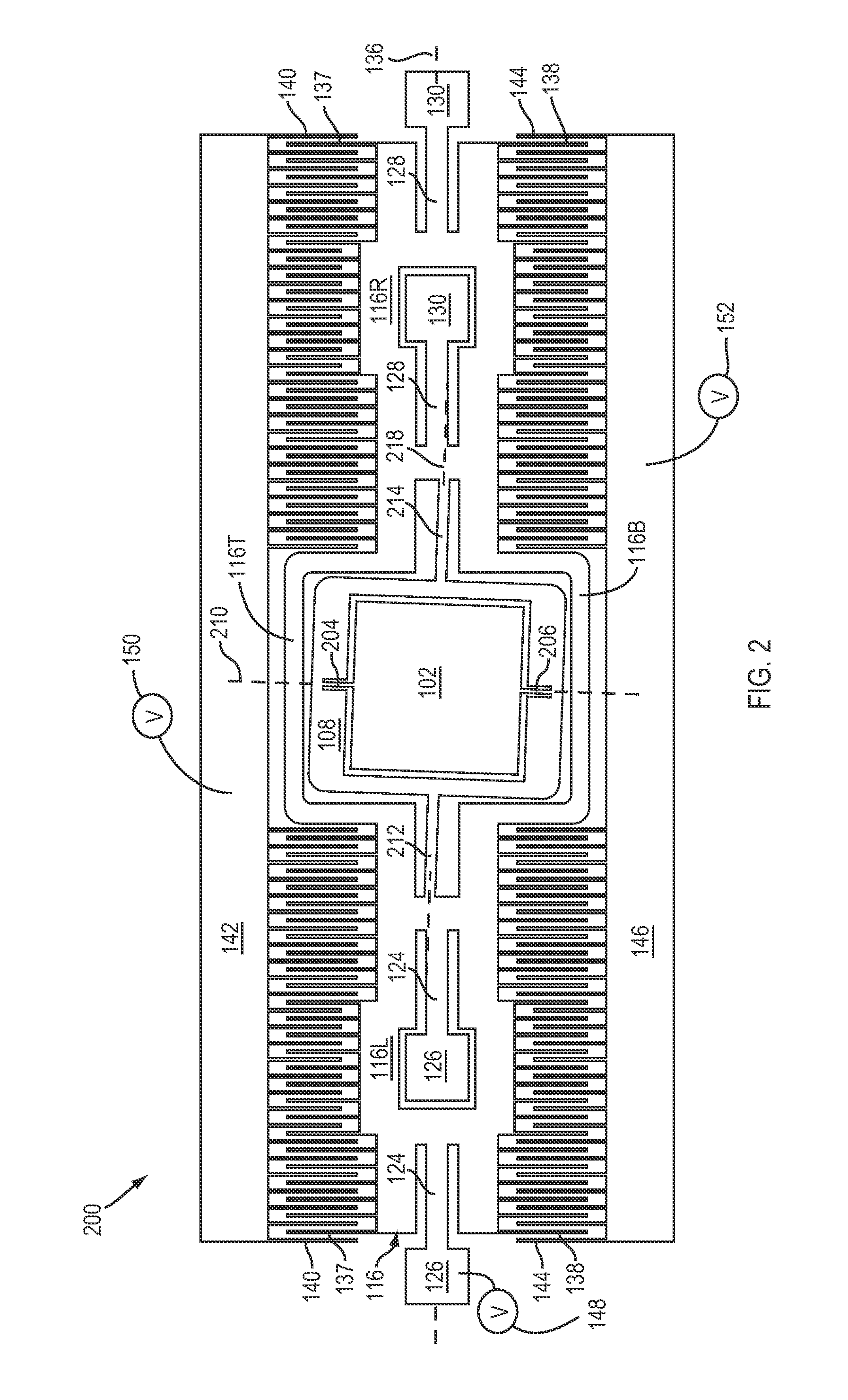
A micro-electro-mechanical system (MEMS) mirror device has a mirror, a frame rotatively coupled to the mirror, and a biaxial actuator rotatively coupled to the frame where the actuator is able to rotate about the rotational axes of the mirror and the frame with the mirror.

Description

CROSS REFERENCE TO RELATED APPLICATIONS[0001]This application is a continuation of U.S. patent application Ser. No. 12 / 392,607, filed on Feb. 25, 2009, now U.S. Pat. No. 8,035,874, and incorporated herein by reference.FIELD OF INVENTION[0002]This invention relates to micro-electro-mechanical system (MEMS) devices, and more particularly to MEMS scanning mirrors.DESCRIPTION OF RELATED ART[0003]U.S. Pat. Nos. 6,769,616 and 7,034,370 disclose a bidirectional scanning MEMS mirror system. In the system, a mirror is rotatively coupled to a frame and the frame is rotatively mounted to an anchor layer. Actuators that consist of electrodes extending from the outer perimeter of the mirror and the inner perimeter of the frame rotate the mirror about a first axis. Actuators that consist of electrode extending from the outer perimeter of the frame and the inner perimeter of stationary pads rotate the frame about a second axis. The result is a rather complicated design of the mirror and the frame ...

Claims


Application Information

Patent Timeline
Patent Type & Authority Patents(United States)
IPC IPC(8): G02B26/08
CPCG02B26/0841Y10S359/90
Inventor FU, YEE-CHUNG
Owner ADVANCED NUMICRO SYST
Learn More