
Ball with camera and trajectory control for reconnaissance or recreation

a technology of trajectory control and ball with camera, applied in the field of spherical projectiles, can solve the problems of inability to change the trajectory of the resilient object, impractical aerodynamic impediments with respect to drag, and further disadvantaged resilience objects

Inactive Publication Date: 2012-08-07
HOLLINGER STEVEN J
View PDF12 Cites 53 Cited by
  • Summary
  • Abstract
  • Description
  • Claims
  • Application Information

AI Technical Summary

Benefits of technology

Enables the capture of high-quality images and videos by ensuring the camera is oriented correctly and positioned optimally relative to the target, while also allowing the ball to adjust its trajectory for improved aerodynamics and image capture, resulting in a more stable and effective image acquisition process.

Problems solved by technology

This resilient object is further disadvantaged by its inability to change its own trajectory.
The inflatable housing and cubic shape of the preferred embodiment present impractical aerodynamic impediments with respect to drag if a pitched or projected airborne trajectory is desired.
As with the resilient object of patent GB2444391, this ball is disadvantaged by its inability to store and analyze successive frames of captured image data.
The ball is further disadvantaged by its inability to capture successive frames of image data captured while spinning or precessing past a ground-based subject in order to produce a meaningful video stream.
This ball is further disadvantaged by its inability to change its own trajectory.
This patent is disadvantaged by requiring external surface-mounted fins to ensure that the camera provides images from a desirable orientation.
This patent is disadvantaged by requiring an external surface-mounted aerodynamic tail to ensure that the camera provides images from a desirable orientation.
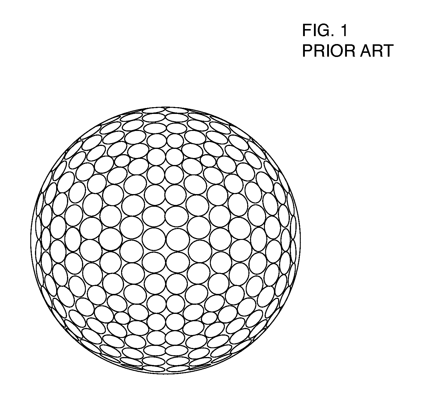
Golf ball dimples produce an undesirable drag at lower windspeeds.
Similarly, the rigid ridges on the upper surface of a Frisbee flying disc produce a desirable increase in lift over a significant portion of the disc's airborne trajectory, but produce an undesirable increase in drag at other portions of the disc's trajectory.

Method used


Image

  • Ball with camera and trajectory control for reconnaissance or recreation
  • Ball with camera and trajectory control for reconnaissance or recreation
  • Ball with camera and trajectory control for reconnaissance or recreation

Examples


Embodiment Construction

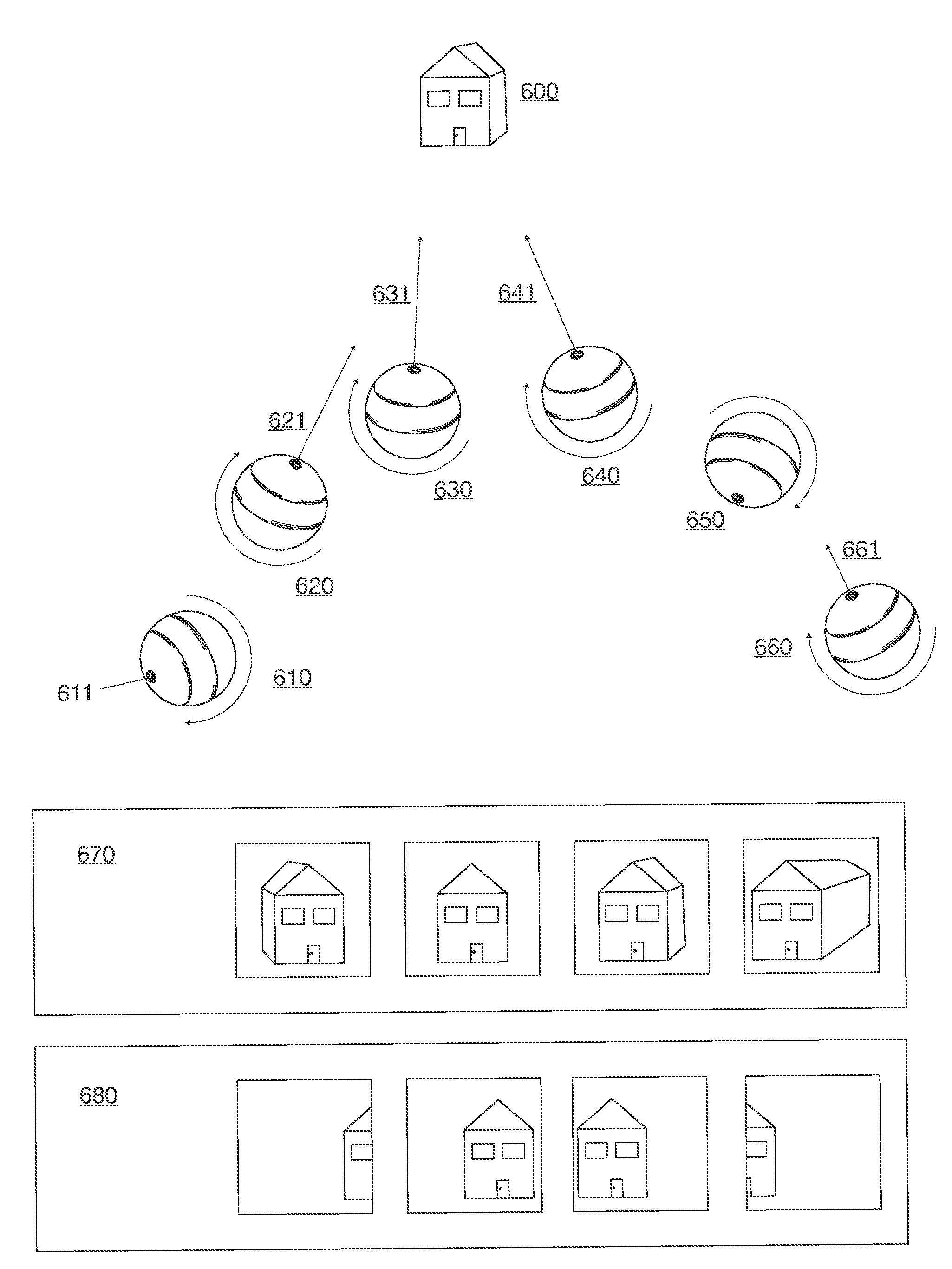
[0054]A ball capable of isolating image capture to a desired subject or perspective and further capable of changing its trajectory in order to improve the capture of video or still images is made possible by the advent of shock-resistant microelectronic GPS sensing packages, gyroscopes and multi-axis accelerometers and the availability of inexpensive high-capacity storage and low-light, high-speed image capture electronics.

[0055]Because the ball of this invention describes the capture of images from the viewpoint of a smooth arc, a video produced by the ball is substantially improved by comparison with conventional means for moving a camera. A movie captured by the ball of this invention would also be easier and faster to produce than one that required the installation of a dolly, a steadicam, a kite, or other unwieldy configuration. Lastly, a movie captured by the ball of this invention would represent a view of environments unavailable to conventional cranes, helicopters or survei...


PUM


Abstract

A ball that provides normalized images of a ground-based target subject captured over the course of the arc of its airborne trajectory. The improvements include a processing unit that compiles multiple images into a smooth continuous fly-by video of the target subject, a processing unit that stitches multiple images captured at a single moment in the ball's trajectory into a panoramic image and further normalizes and compiles multiple panoramic images into a smooth, continuous fly-through video, and an embedded motion sensor to initiate operations when the ball is pitched, and an embedded impact sensor to shut down operations for power conservation, and a mass which forces the camera into a repeated spinning or precessing orbit around the core of the ball, and a wireless transmission of surveillance imagery captured by the ball, and ground-based transmission of the target subject's location for subsequent image capture, and means for capturing multiple images of varying viewpoints including a camera aperture connected to a branching collection of fused fiber optic bundles. Also disclosed are means for directing the ball along a controllable trajectory to move toward a ground-based target subject.

Description

CROSS-REFERENCE TO RELATED APPLICATIONS[0001]The present application claims priority to U.S. Provisional Patent Application Ser. No. 61 / 174,994, filed May 2, 2009, and U.S. Provisional Patent Application Ser. No. 61 / 177,769, filed on May 13, 2009 and also, U.S. Provisional Patent Application Ser. No. 61 / 226,618, filed on Jul. 17, 2009. The entire contents of these applications are herein incorporated by reference.STATEMENT REGARDING FEDERALLY SPONSORED RESEARCH DEVELOPMENT[0002]Not applicable.BACKGROUND OF THE INVENTION[0003]1. Field of the Invention[0004]The invention has generally to do with spherical projectiles capable of sensing their spatial location and orientation while in an airborne trajectory, and more particularly a ball capable of using location and orientation information to move towards and capture images of a particular ground-based subject of interest.[0005]2. Description of Related Art[0006]Projectiles with embedded cameras, including spherical ball-shaped cameras,...

Claims


Application Information

Patent Timeline
Patent Type & Authority Patents(United States)
IPC IPC(8): H04N5/253H04N7/18H04N5/225
CPCH04N5/2252H04N5/232H04N5/23238H04N23/50H04N23/51H04N23/60A63B43/004A63B2220/833A63B2220/16A63B2220/801A63B2220/803A63B2220/806A63B2220/807A63B37/0003A63B43/00A63B43/04H04N23/698H04N23/555A63B24/0021A63B2024/0034
Inventor HOLLINGER, STEVEN J.
Owner HOLLINGER STEVEN J
Learn More