Data structure representing a plenoptic function via compressible layered orthographic projections from multiple orientations

a data structure and plenoptic function technology, applied in the field of graphical imaging, can solve problems such as the potential to compress to an even greater degree, and achieve the effects of facilitating the access to such information, fast rendering, and new information

Inactive Publication Date: 2012-08-07
MANTZEL WILLIAM EDWARD
View PDF5 Cites 12 Cited by
  • Summary
  • Abstract
  • Description
  • Claims
  • Application Information

AI Technical Summary

Benefits of technology

[0015]The access of such information will be greatly facilitated by its locality and relatively small number of representative directions, so that new views may be quickly rendered. Furthermore, when a given spatial area is divided up into regions with multiple spatial scales with larger regions having lower spatial resolution, it will be feasible to quickly render nearby objects with a fine spatial resolution and faraway objects with a coarse spatial resolution, thereby overcoming a common limitation of using orthographic images for perspective rendering.

Problems solved by technology

Even still, the representation may have many correlated and redundant samples when completely uncompressed, but will often have the potential to compress to an even greater degree than existing approaches (for equal degrees of representative fidelity).

Method used


Image

  • Data structure representing a plenoptic function via compressible layered orthographic projections from multiple orientations
  • Data structure representing a plenoptic function via compressible layered orthographic projections from multiple orientations
  • Data structure representing a plenoptic function via compressible layered orthographic projections from multiple orientations

Examples


Embodiment Construction

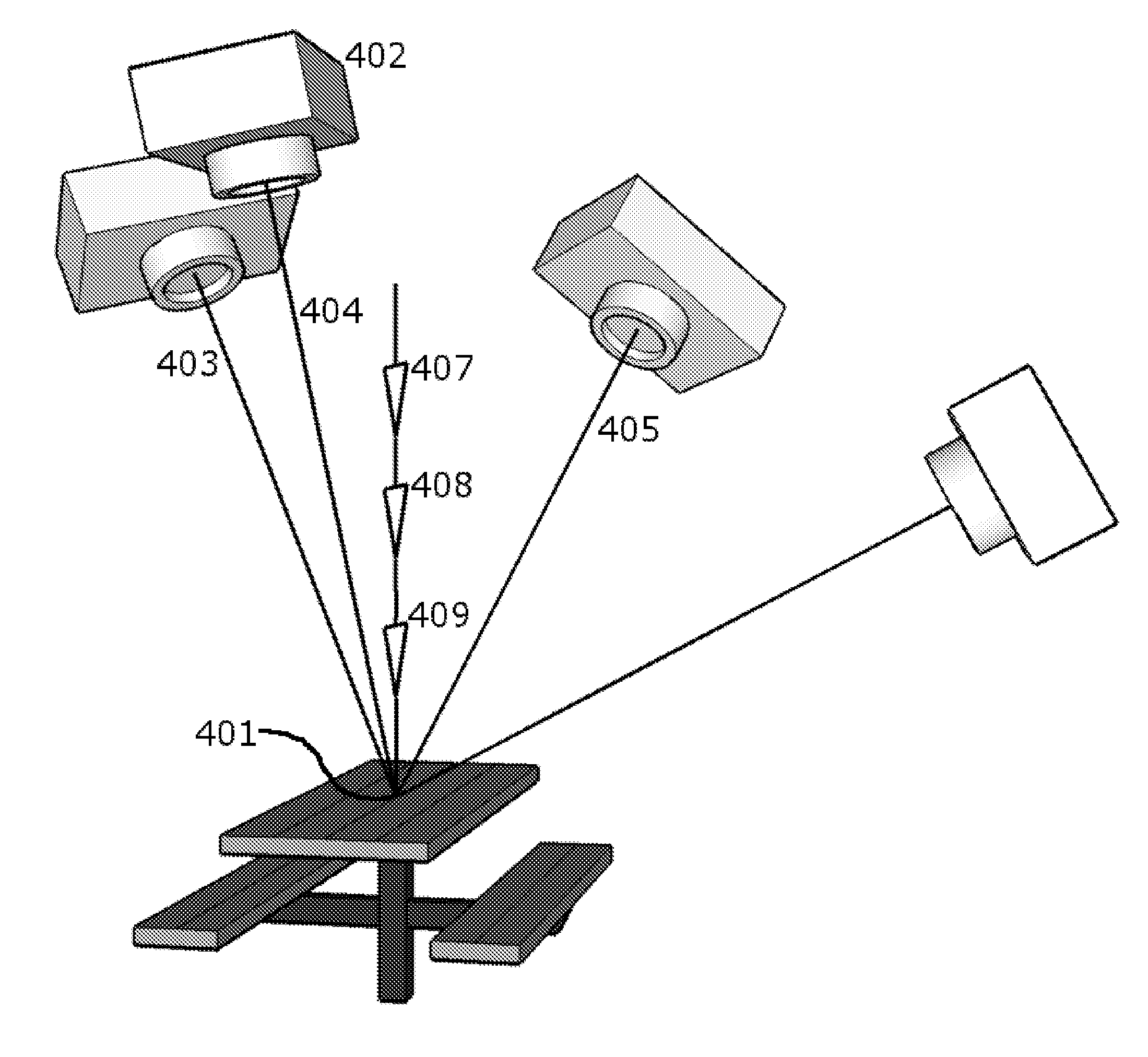
[0021]This invention essentially stores luminance information. The choice of representation for this light field information and depth field information constitutes the most substantial innovation described here. However, for illustrative purposes, the description will also discuss the user's choice of coordinate system, describe a scheme for partial compression, and give a cursory description of how rendering and other operations are facilitated is given to show how this choice of representation will be conducive for such operations.

A. Light Field Sampling

[0022]This light field representation is divided into a set of coordinate systems O for purposes of sampling. This set of coordinate systems is usually chosen to coincide at least partially with the inherent coordinate system of this region, e.g. the coordinate system of buildings and streets or the local direction of gravity. In coordinate system o, the 3-D coordinates of a given point are given as {right arrow over (X)}0=[xo, yo...


PUM


Abstract

A novel layered orthographic representation of the light field, comprising a set of 3-D orientations, each orientation having an associated depth direction and two sampling directions, each such orientation being associated with a set of planar grids normal to the depth direction and containing grid points evenly sampled along the sampling directions, each grid containing orthographic samples of the light field intercepting that grid point in the direction of the associated depth direction. Information of the geometric structure is similarly stored in depth field format at these sample points.

Description

CROSS-REFERENCE TO RELATED APPLICATION[0001]This application claims the benefit of U.S. provisional patent application Ser. No. 60 / 822,828, filed Aug. 18, 2006 by William Mantzel, which is incorporated herein by reference.FIELD OF THE INVENTION[0002]The present invention relates to the field of graphical imaging, and particularly image-based rendering. Specifically, it relates to the representation of light field information when information of the geometrical structure of the scene is available.BACKGROUND OF THE INVENTION[0003]In early computer vision and computer graphics approaches, environments were rendered visually by means of meshes constructed of polygons with individual properties of color and reflectance. In order to construct more photorealistic renderings, researchers soon began to explore ways to use the pixel values of actual images, giving rise to the field of image-based rendering. Some researchers explored ways to interpolate between images, while others explored me...

Claims


Application Information

Patent Timeline
Patent Type & Authority Patents(United States)
IPC IPC(8): G06T15/40
CPCG06K9/28G06T15/205G06V30/144
Inventor MANTZEL, WILLIAM EDWARD
Owner MANTZEL WILLIAM EDWARD
Why Eureka
Try Eureka