Method for detecting an electric potential-difference at a piezoelectric actuator unit, and a circuit system for implementing the method

a piezoelectric actuator and electric potential-difference technology, applied in the direction of electric control, machines/engines, instruments, etc., can solve the problems of not being able to reliably monitor the voltage at the piezoelectric element, without ground potential, and no piezoelectric element terminal is connected to ground, etc., to achieve high time resolution, high amplitude resolution, and reliable monitoring of piezoelectric elements

Inactive Publication Date: 2012-08-07
ROBERT BOSCH GMBH
View PDF7 Cites 2 Cited by
  • Summary
  • Abstract
  • Description
  • Claims
  • Application Information

AI Technical Summary

Benefits of technology

[0011]Using such a device for monitoring differential voltage, it is possible to reliably monitor piezoelectric elements that are used in piezo common rail diesel systems having an injector with a direct needle control, for example. Advantageously, a processing device processes the first and second potential-difference signals in such a manner that a control signal having a high amplitude resolution and / or a high time resolution is obtained.

Problems solved by technology

Indeed, in the case of an error, a fast discharge of the piezoelectric element may be ensured; however, disadvantageously, using the described system it is not possible to monitor a voltage at the piezoelectric element reliably and without ground potential.
However, in the further refinement of piezoelectric elements for highly precise fuel injection, none of the terminals of the piezoelectric element is connected to ground.
It is problematic if such a potential of less than 45 V is also applied to a terminal on the high voltage side, since then the differential voltage at the actuator becomes negative.

Method used


Image

  • Method for detecting an electric potential-difference at a piezoelectric actuator unit, and a circuit system for implementing the method
  • Method for detecting an electric potential-difference at a piezoelectric actuator unit, and a circuit system for implementing the method

Examples


Embodiment Construction

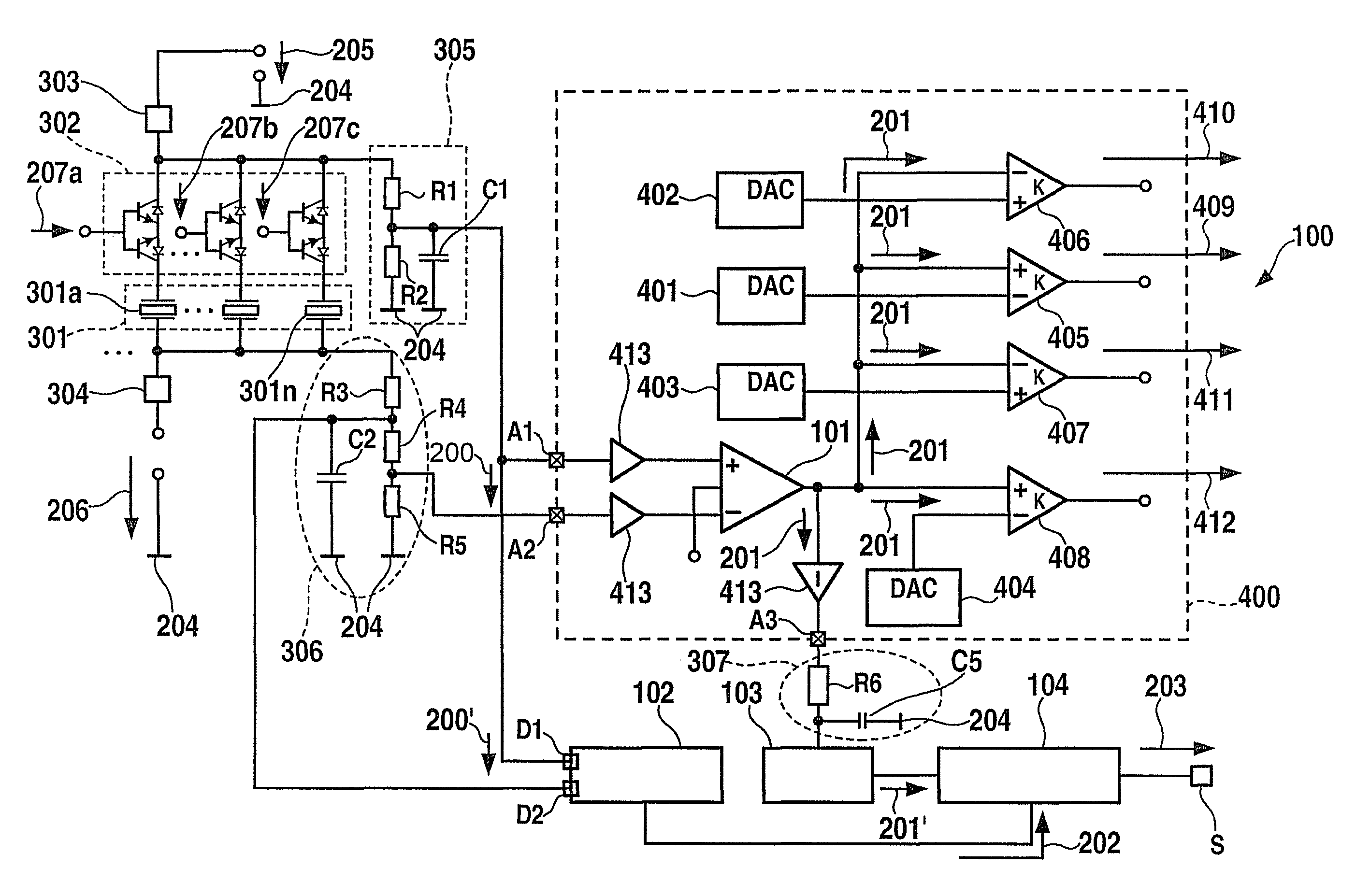
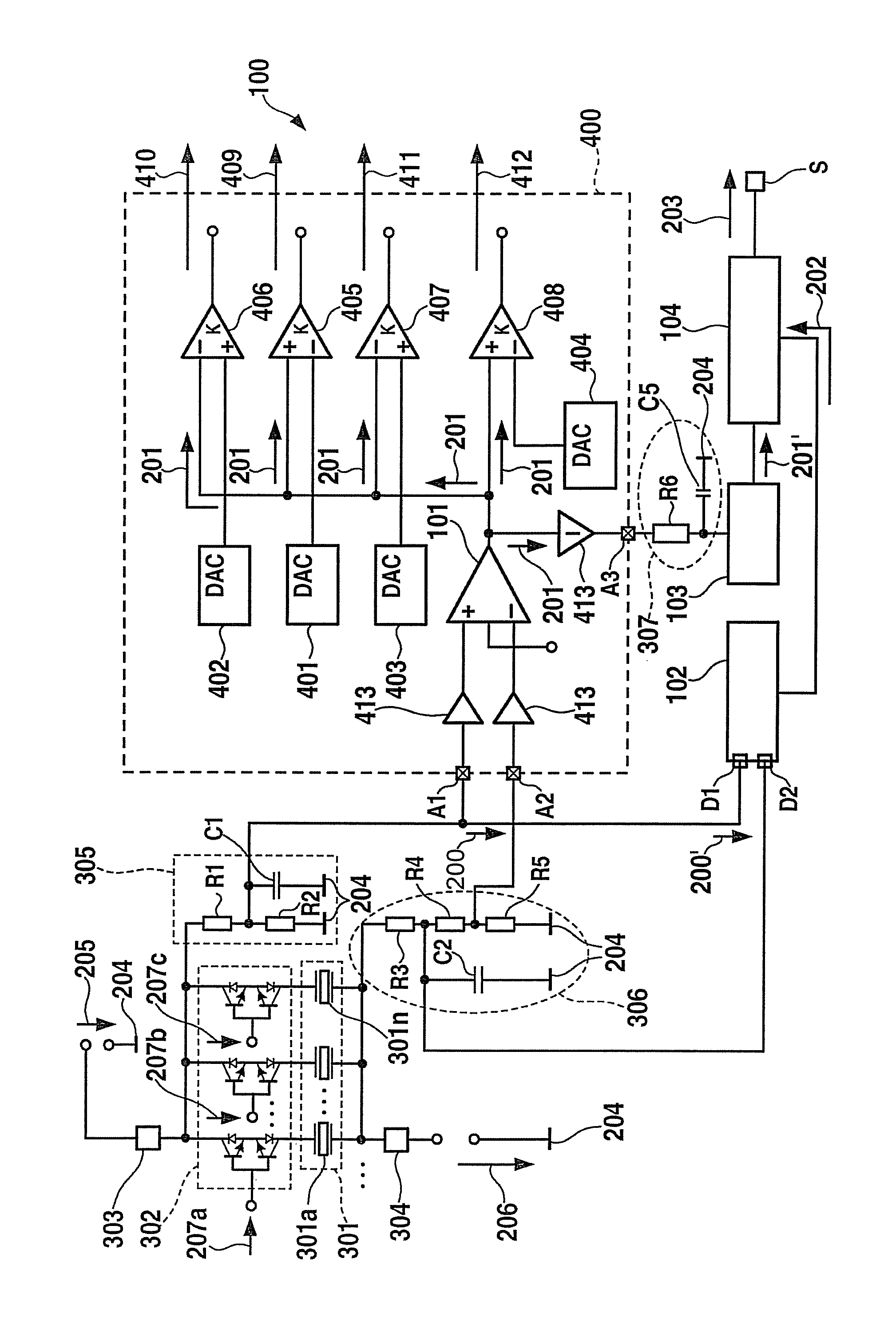
[0028]FIG. 1 shows a block diagram of a circuit system for detecting a time-variable amplitude of at least one potential-difference 200 to be detected in accordance with one exemplary embodiment of the present invention. Circuit system 100 shown in FIG. 1 has a control device 400 for providing switching control signals 409-412, which may be generated as a function of a potential-difference signal.

[0029]In accordance with the exemplary embodiment of the present invention shown in FIG. 1, circuit system 100 is used to monitor the differential voltage at an actuator unit 301. Actuator unit 301 is controlled via an actuator control unit 302, actuator control unit 302 receiving externally specified actuator control signals 207a, 207b, 207c. To operate actuator unit 301, a first actuator supply voltage 205 with respect to a ground potential 204 is applied at a first supply voltage terminal 303, and a second actuator supply voltage 206 with respect to ground potential 204 is applied at a s...


PUM


Abstract

A circuit system for detecting a time-variable amplitude via an electric potential-difference to be detected. A first potential-difference detection device for detecting the at least one electric potential-difference and for outputting a first potential-difference signal, and a second potential-difference detection device for detecting the at least one electric potential-difference and for outputting a second potential-difference signal are provided. The first potential-difference detection device has a higher time resolution than the second potential-difference detection device, while the second potential-difference detection device has a higher amplitude resolution than the first potential-difference detection device.

Description

FIELD OF THE INVENTION[0001]The present invention relates to a circuit system for driving a piezoelectric element, and in particular relates to a circuit system and a method for monitoring the piezoelectric element. Specifically, the present invention relates to a circuit system for detecting a time-variable amplitude of at least one electric potential-difference to be detected, having a first potential-difference detection device for detecting the at least one electric potential-difference and for outputting a first potential-difference signal, and a second potential-difference detection device for detecting the at least one electric potential-difference and for outputting a second potential-difference signal.BACKGROUND INFORMATION[0002]Control devices for piezoelectric elements are used in fuel injection systems of a motor vehicle, for example. In this connection, piezoelectric elements of this type are used as an actuator to which a control current may be applied. For the control...

Claims


Application Information

Patent Timeline
Patent Type & Authority Patents(United States)
IPC IPC(8): G01R1/38
CPCG01R19/0084F02D41/2096F02D41/221G01R19/2503H01L41/042H10N30/802
Inventor FUCHS, STEFANGRAF, MARCO
Owner ROBERT BOSCH GMBH
Why Eureka
Try Eureka