Reinforced mull post assembly

a composite and mull post technology, applied in the field of mull posts, can solve the problems of compromising the integrity of hardware fasteners, post withstand, entryway, etc., and achieve the effect of enhancing at least one of a structural strength and a rigidity of the mull post profil

Active Publication Date: 2012-07-31
PLASTPRO 2000
View PDF20 Cites 17 Cited by
  • Summary
  • Abstract
  • Description
  • Claims
  • Application Information

AI Technical Summary

Benefits of technology

[0008]A reinforced mull post is disclosed. The reinforced mull post may comprise a mull post profile comprising an elongated support portion and a stop portion. The support portion may have first and second support faces, and the stop portion may have first and second legs forming first and second raised stops laterally offset from said first and second support faces, respectively. The mull profile may further comprise a hollow central chamber extending within the support portion and the stop portion. The mull profile may have a first reinforcing member disposed within the hollow central chamber; and a second reinforcing member disposed within the hollow central chamber in cooperation with the first reinforcing member. The second reinforcing member may be made from a material that is different from that of the first reinforcing member. The first and second reinforcing members may enhance a structural strength and a rigidity of the mull post profile.
[0009]A reinforced mull post is further disclosed, comprising an extruded mull post profile having an elongated support portion and a stop portion. The support portion may have first and second support faces, and the stop portion may have first and second legs forming first and second raised stops laterally offset from said first and second support faces, respectively. A first reinforcing member may be disposed within a hollow central chamber of the extruded mull post profile. A second reinforcing member may be disposed within the hollow central chamber. The second reinforcing member may comprise a material different from that of the first reinforcing member. The first and second reinforcing members may enhance at least one of a structural strength and a rigidity of the mull post profile.
[0010]A reinforced mull post assembly is disclosed, comprising a polymer mull post having an elongated support portion and a stop portion. The support portion may have first and second support faces, and the stop portion may have first and second legs forming first and second raised stops laterally offset from said first and second support faces by first and second slots, respectively. A first reinforcing member may be disposed within a hollow central chamber of said polymer mull post. The first reinforcing member enhances at least one of a structural strength and a rigidity of the mull post.

Problems solved by technology

While such construction is acceptable in many regions, it generally does not result in mull posts that can withstand the extreme weather conditions that often occur in coastal areas.
For instance, when an entryway having traditional wood mull posts is exposed to the high pressures from wind forces that entryways in coastal areas may experience, the forces transferred through the door to the mull posts can cause the mulls, and thus the entryway, to fail.
Further, the high pressure can cause the mulls to deflect or bend, compromising the integrity of hardware fasteners.
Thus, traditional finger jointed wood mull posts are not acceptable for use in regions with stringent design pressure requirements.
Even where solid wood mull designs are used to eliminate failure at finger joint locations, problems caused by splitting of the wood along its grain remain.
While polymer mull posts may not be as susceptible to breaking or splitting like traditional wood mulls, they still may be highly susceptible to deflection or bending when exposed to high pressure, thus compromising the integrity of the entryway system as previously explained.
Traditional solid wood mull posts and extruded polymer mulls may be highly vulnerable to such impacts, again, for the reasons previously stated.

Method used


Image

  • Reinforced mull post assembly
  • Reinforced mull post assembly
  • Reinforced mull post assembly

Examples


Embodiment Construction

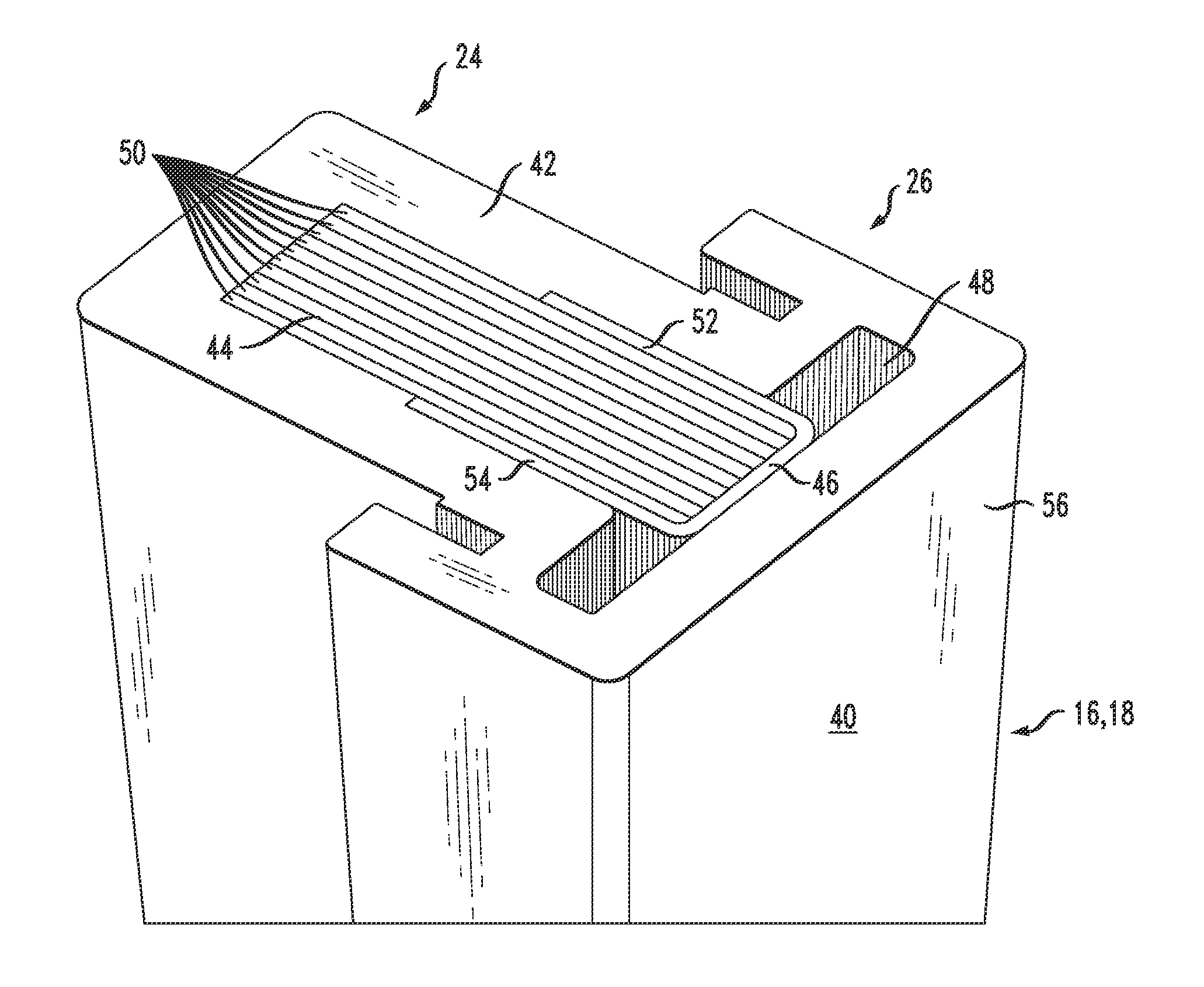
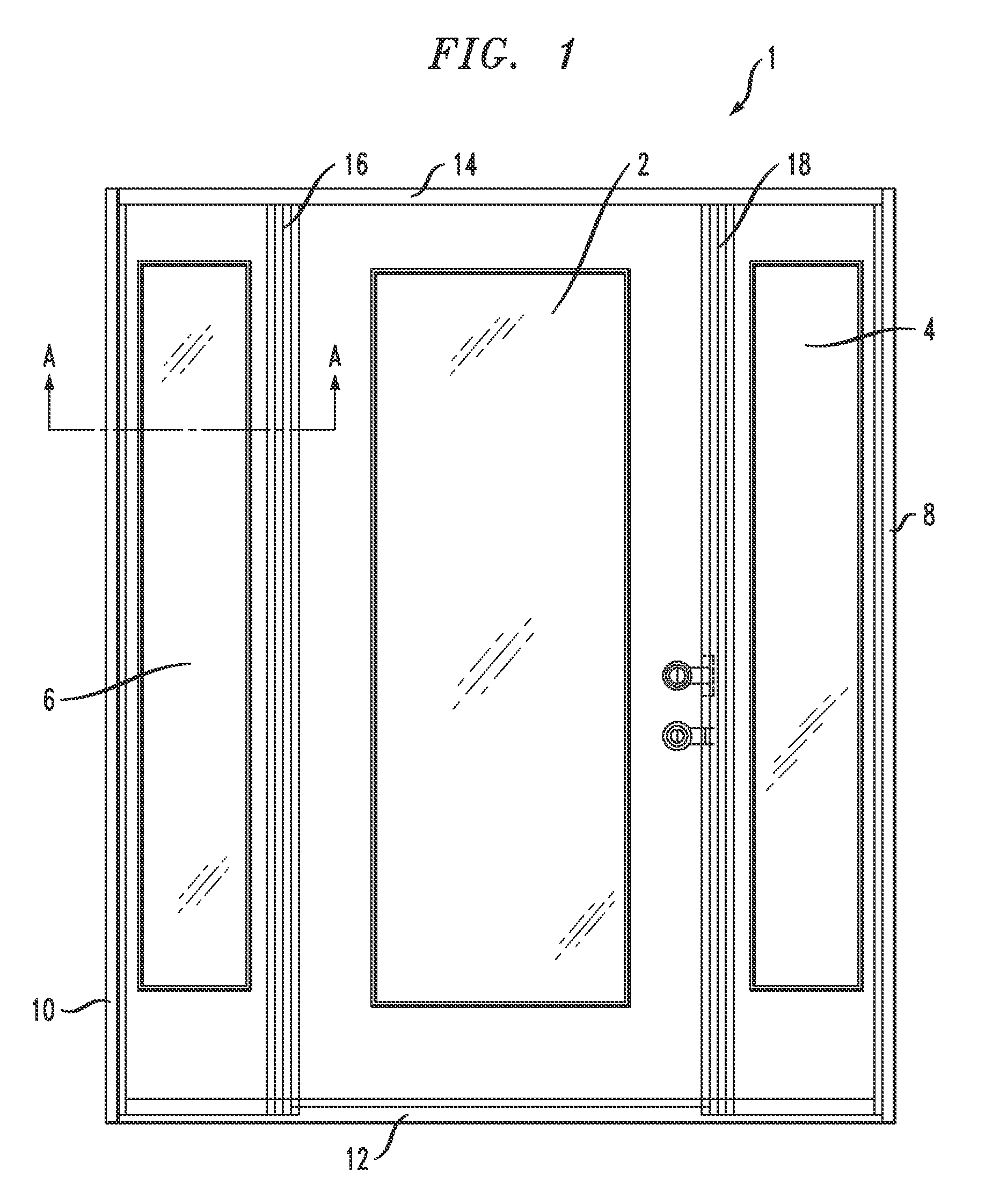
[0016]Referring to FIG. 1, a typical exterior door assembly 1 comprises a central hinged door 2 and side light window panels 4, 6 that flank the door on either side. The exterior door assembly 1 further comprises a pair of vertical door jambs 8, 10 that extend between a sill 12 and a header 14. Together, the jambs 8, 10, the sill 12 and header 14 define the outer peripheral frame of the exterior door assembly 1. A pair of spaced mull posts 16, 18 extend vertically between the sill 12 and the header 14 and define a central opening in which the hinged door 2 is disposed, as well as two flanking side openings on either side of the door for receiving the side light window panels 4, 6.

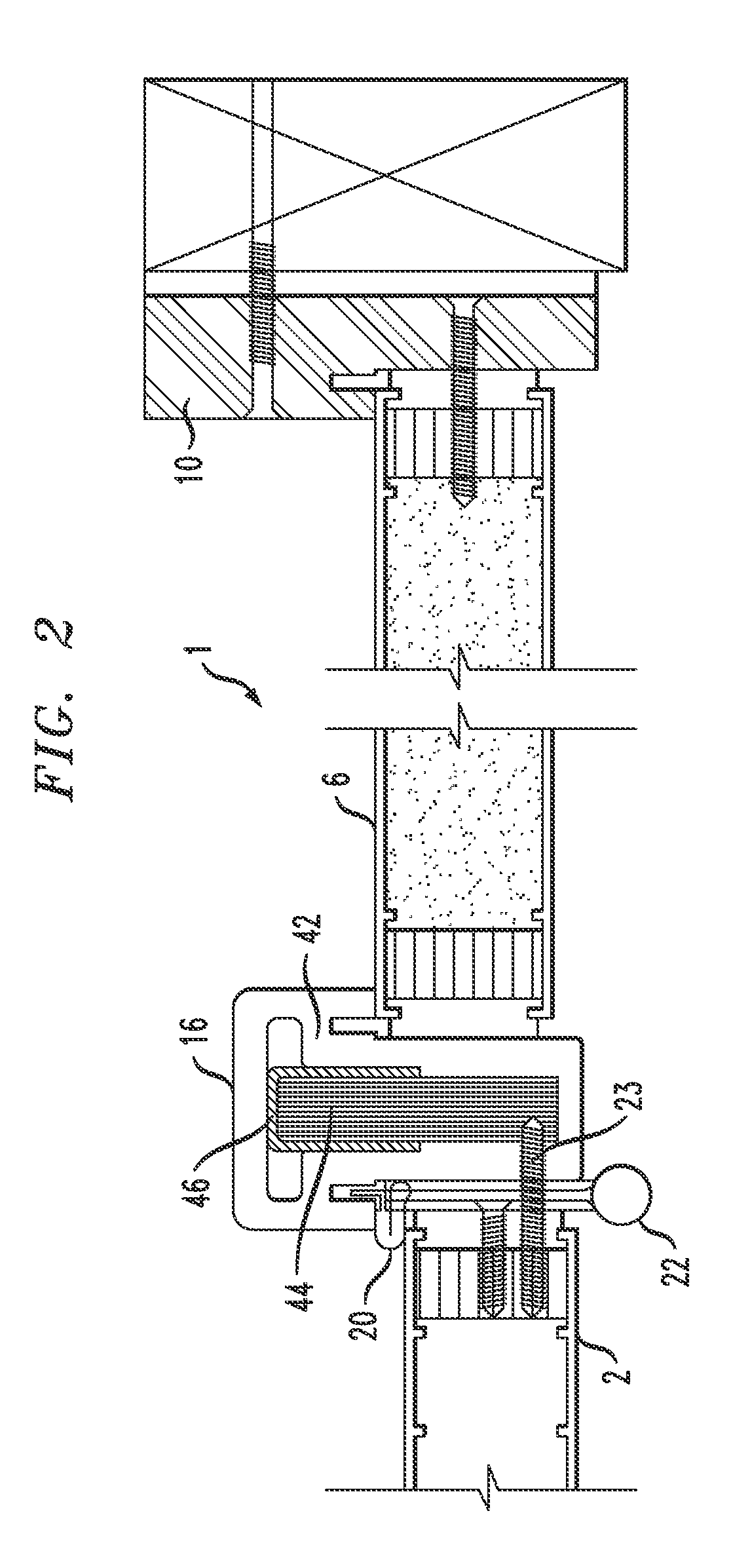
[0017]Referring to FIG. 2, a partial cross-section of the door assembly 1 is shown. As can be seen, the left-most mull post 16 is positioned between the left-most side light window panel 6 and the door 2. A piece of weather-stripping 20 is engaged between the mull post 16 and the door 2, and a door hinge 22...


PUM

PropertyMeasurementUnit
thicknessaaaaaaaaaa
thicknessaaaaaaaaaa
widthaaaaaaaaaa

Abstract

A composite reinforced mull post is disclosed or use in an exterior building entryway assembly, engaging a door on one side and a side light window on the other side. The mull post may comprise a polymer profile portion and first and second reinforcing members. The profile portion comprises a layer of polyvinyl chloride with a hollow center. The first reinforcing member comprises an engineered material such as a wood laminate, and the second reinforcing member comprises a U-shaped steel channel that fits around one end of the first reinforcing member. The reinforcing members are received within the hollow center of the polymer profile portion and run the entire length of the mull post to provide substantial rigidity to the assembly. A polymer cap layer may be co-extruded on the outer surface of the polymer profile portion to provide the mull post with a desired finished surface appearance and / or color.

Description

CROSS-REFERENCE TO RELATED APPLICATIONS[0001]This is a non-provisional of co-pending U.S. provisional patent application Ser. No. 61 / 148,652, filed Jan. 30, 2009, the entirety of which application is incorporated by reference herein.FIELD OF THE INVENTION[0002]The disclosure relates generally to mull posts for use in exterior door assemblies, and more particularly to a reinforced composite mull post for use in an exterior door assembly.BACKGROUND OF THE INVENTION[0003]Entryway systems used in residential and commercial buildings include single and double door assemblies having one or more sidelights or sidelight panels flanking the door(s). Such entryway systems are typically fabricated using vertical mullions or mull posts positioned between the door(s) and the associated sidelight or sidelight panel to connect the structures. When these entryway systems are used in coastal regions of the country, it is desirable that the systems be capable of withstanding the extremely high pressu...

Claims


Application Information

Patent Timeline
Patent Type & Authority Patents(United States)
IPC IPC(8): E06B1/04E04C1/00
CPCE06B1/32E06B1/524E06B3/222
Inventor AN, PAO YU
Owner PLASTPRO 2000
Why Eureka
Try Eureka