
Pressure sensitive switch and input device using pressure sensitive switch

a technology of pressure sensitive switch and input device, which is applied in the direction of static indicating device, instruments, contacts, etc., can solve the problems of disturbed smooth operation, and achieve the effect of smooth operation, high accuracy and simple manner

Inactive Publication Date: 2012-07-24
PANASONIC CORP
View PDF12 Cites 7 Cited by
  • Summary
  • Abstract
  • Description
  • Claims
  • Application Information

AI Technical Summary

Benefits of technology

"The present invention provides a pressure sensitive switch and an input device using it. The switch is simple to operate and can perform various functions. It includes a cover, a slide portion, a pressing unit, a sheet resistive body, and a conductive plate. The slide portion can be pressed in a horizontal direction, and the pressing unit can move the sheet resistive body. The resistance value between the sheet resistive body and the conductive plate changes when the slide operation force changes. This allows for smooth operation regardless of the movement direction of the cursor displayed on the screen. The input device includes the pressure sensitive switch, a switch unit, a control unit, and a constant voltage power supply. The control unit can estimate the pressing direction based on the input voltage through the conductive plate. This allows for accurate detection of the operator's direction of pressing. Overall, this invention provides a pressure sensitive switch and an input device that are easy to use and capable of performing various functions."

Problems solved by technology

Therefore, there is a problem in that a smooth operation is disturbed.

Method used


Image

  • Pressure sensitive switch and input device using pressure sensitive switch
  • Pressure sensitive switch and input device using pressure sensitive switch
  • Pressure sensitive switch and input device using pressure sensitive switch

Examples


embodiment 1

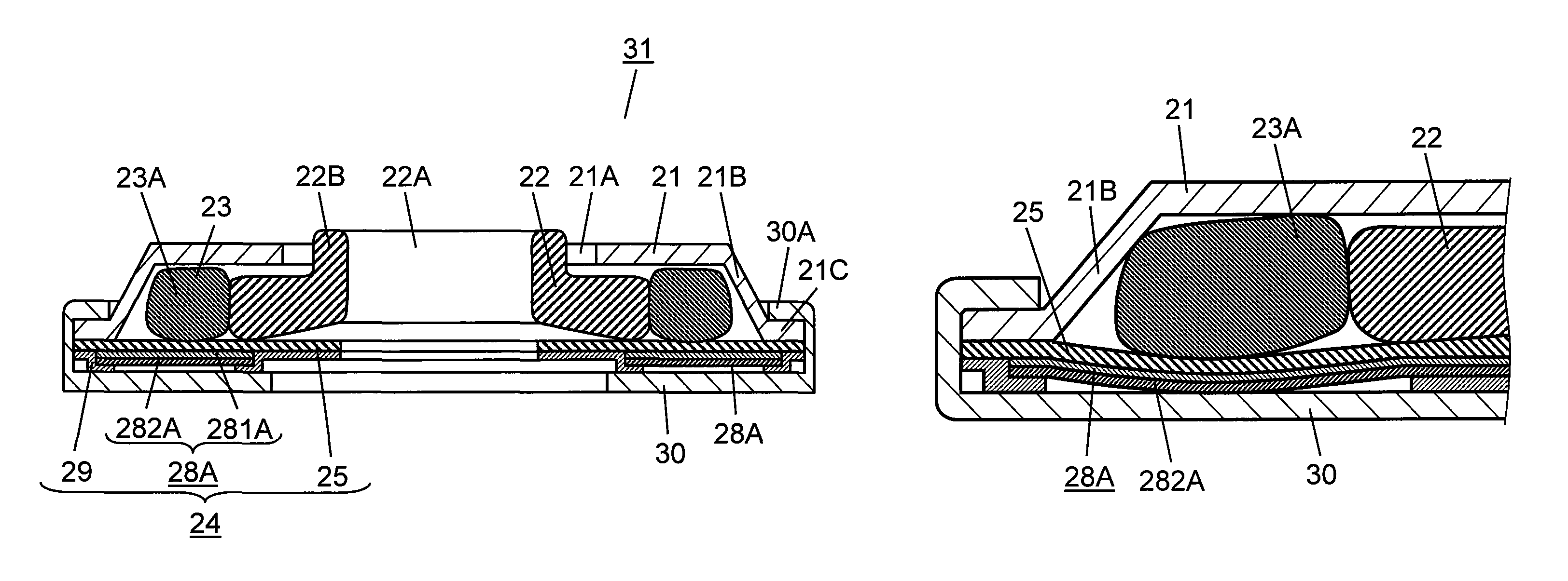
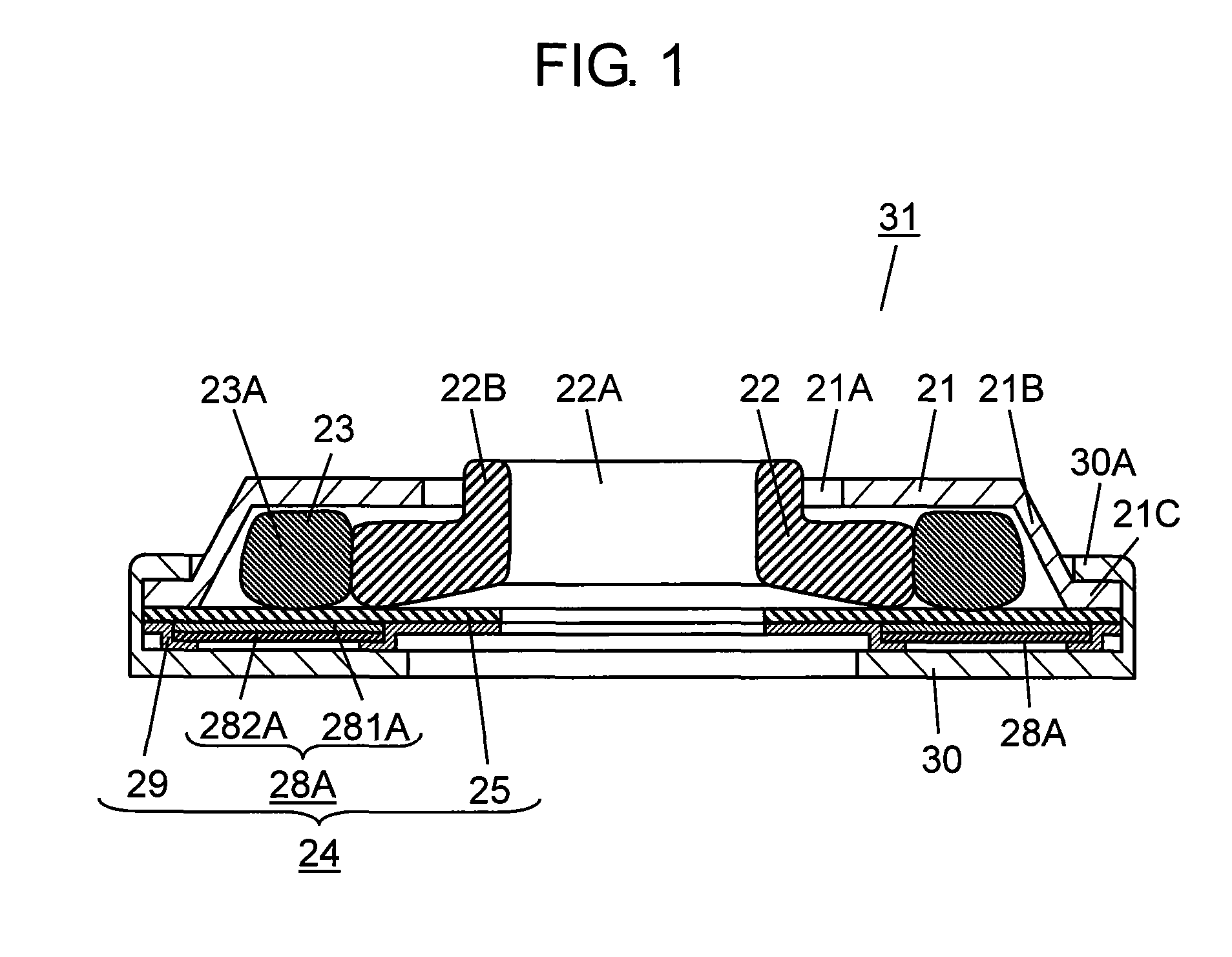
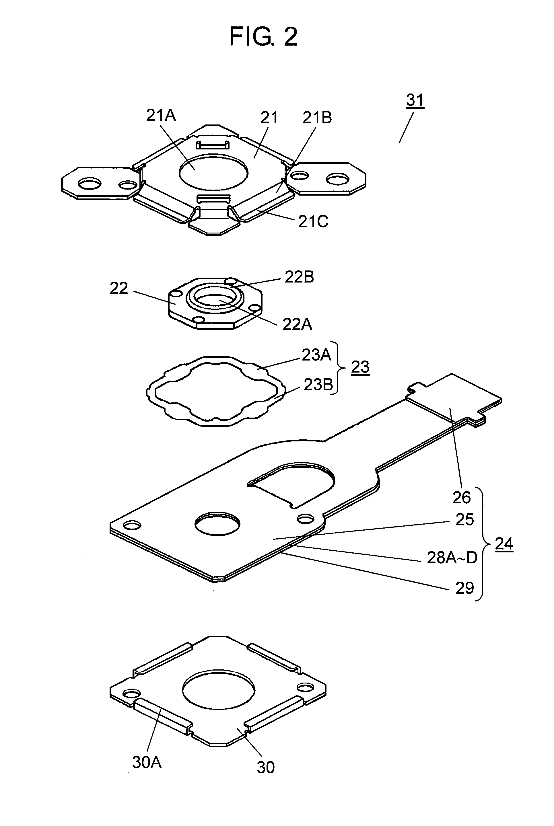
[0048]FIG. 1 is a cross-sectional view of a pressure sensitive switch according to Embodiment 1 of the present invention. FIG. 2 is an exploded perspective view of the pressure sensitive switch according to Embodiment 1 of the invention. As shown in FIGS. 1 and 2, cover 21 that is formed from metal such as stainless steel has an open lower face side. Circular hole 21A is formed at the center of the top face of cover 21, and on the inner face of cover 21, inclined face portion 21B that forms an inclined face broadened toward the outer side is disposed. In the outer frame of inclined face portion 21B, frame portion 21C that protrudes in a direction parallel to the top face is formed.

[0049]In addition, slide portion 22, which is made of insulating resin such as nylon, formed in an octagon shape in the top view is stored in cover 21 in the lower direction of cover 21. In addition, on the approximate center of slide portion 22, circular hole 22A that has an opening area smaller than that...

embodiment 2

[0107]Hereinafter, Embodiment 2 of the present invention will be described. To each portion having the same configuration as that of Embodiment 1, a same reference sign is assigned, and the description thereof is omitted here.

[0108]FIG. 14 is an exploded perspective view of pressure sensitive conduction unit 81 according to Embodiment 2. Base sheet 82 having a film shape has flexibility and is formed to have one end positioned on the right side to extend. Base sheet 82 is formed of polyethyleneterephthalate, polycarbonate, polyimide, or the like. Base sheet 82 includes circular hole 82A disposed in an approximate center position of the left half face and connector cover 83, which is formed of insulating resin, on the extended right end of the base sheet.

[0109]In addition, on the lower face of base sheet 82, a plurality of lines 84 are disposed. The lines 84 are formed by printing a conductive material such as silver paste or processing conductive metal by using an etching process, a...


PUM


Abstract

There is provided a pressure sensitive switch including: a cover; a slide portion that is stored in the cover and is slidable by being pressed in a horizontal direction; a pressing unit including a pressure portion that has an inner side face brought into contact with the slide portion and can be moved by being pressed by the slide potion; a sheet resistive body that has an upper face brought into contact with the pressing unit; and a conductive plate that is disposed on the lower side of the sheet resistive body with a predetermined gap arranged therebetween. The slide portion is slidable within a horizontal plane, and the pressing portion presses the sheet resistive body by sliding the slide portion, and a resistance value between the sheet resistive body and the conductive plate changes in accordance with a change in a slide operation force for sliding the slide portion.

Description

BACKGROUND OF THE INVENTION[0001]1. Field of the Invention[0002]The present invention relates to a pressure sensitive switch used mainly for operating various electronic devices and an input device using the pressure sensitive switch.[0003]2. Description of the Related Art[0004]Recently, in accordance with improved functions and diversification of various electronic devices such as cellular phones and car navigation devices, pressure sensitive switches used in such operations and input devices using the pressure sensitive switches require a high operation speed and easiness for use.[0005]Such conventional pressure sensitive switches and input devices using the pressure sensitive switch will be described with reference to FIGS. 20 to 22. For easy understanding of the configuration thereof, in the diagrams, the size in the thickness direction is represented with being enlarged.[0006]FIG. 20 is a cross-sectional view of a conventional pressure sensitive switch, and FIG. 21 is an explod...

Claims


Application Information

Patent Timeline
Patent Type & Authority Patents(United States)
IPC IPC(8): H01C10/10G06F3/0338G06F3/0354
CPCH01H25/041H01H2205/034H01H2215/004
Inventor YOSHIHARA, SATOSHISAWADA, MASAKIKUSUNOKI, HISANORIINOUE, HIROTO
Owner PANASONIC CORP
Learn More