
Method for making a continuous laminate, in particular suitable as a spar cap or another part of a wind energy turbine rotor blade

a technology of continuous laminates and fiber reinforced materials, which is applied in the manufacture of final products, machines/engines, manufacturing tools, etc., can solve the problems of less rigid and stable structural elements, insufficient mechanical connection of adjacent layers of laminates, etc., and achieve the effect of reducing the flow drag of entering

Active Publication Date: 2012-07-24
LM WIND POWER US TECH APS
View PDF10 Cites 29 Cited by
  • Summary
  • Abstract
  • Description
  • Claims
  • Application Information

AI Technical Summary

Benefits of technology

[0007]The above-mentioned problem is solved by a method for making a continuous laminate, in particular suitable as a spar cap or another part of a wind energy turbine rotor blade, the method comprising the steps of

Problems solved by technology

This results in an insufficient mechanical connection of adjacent layers of the laminates, and, accordingly, in a less rigid and stable structural element of the rotor blade or another part made from the fiber reinforced laminates by the infusion process.

Method used


Image

  • Method for making a continuous laminate, in particular suitable as a spar cap or another part of a wind energy turbine rotor blade
  • Method for making a continuous laminate, in particular suitable as a spar cap or another part of a wind energy turbine rotor blade
  • Method for making a continuous laminate, in particular suitable as a spar cap or another part of a wind energy turbine rotor blade

Examples


Embodiment Construction

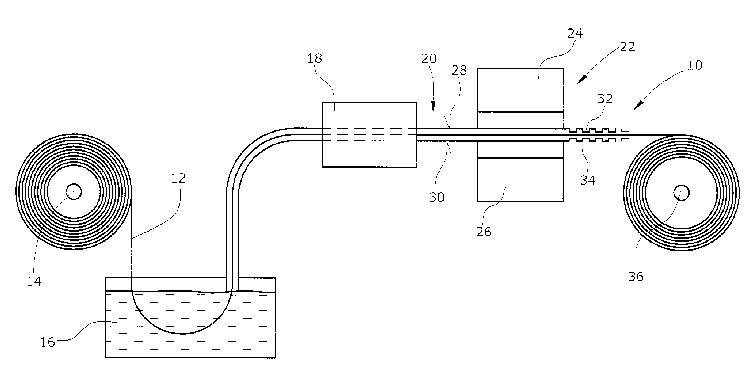
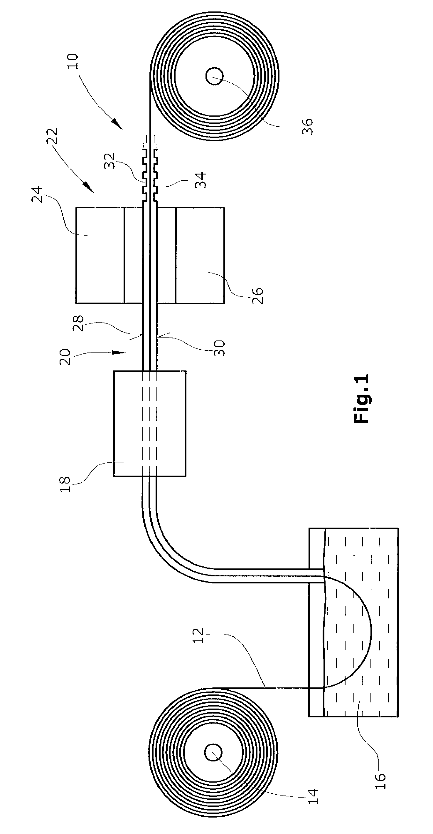
[0022]FIG. 1 shows the individual steps of a first embodiment of a method for making a fiber reinforced continuous laminate 10. A plurality of substantially parallel glass or carbon fibers 12 are drawn from a roll 14 through a bath 16 of epoxy resin. However, other curable materials in which the fibers 12 are embedded, can also be used.

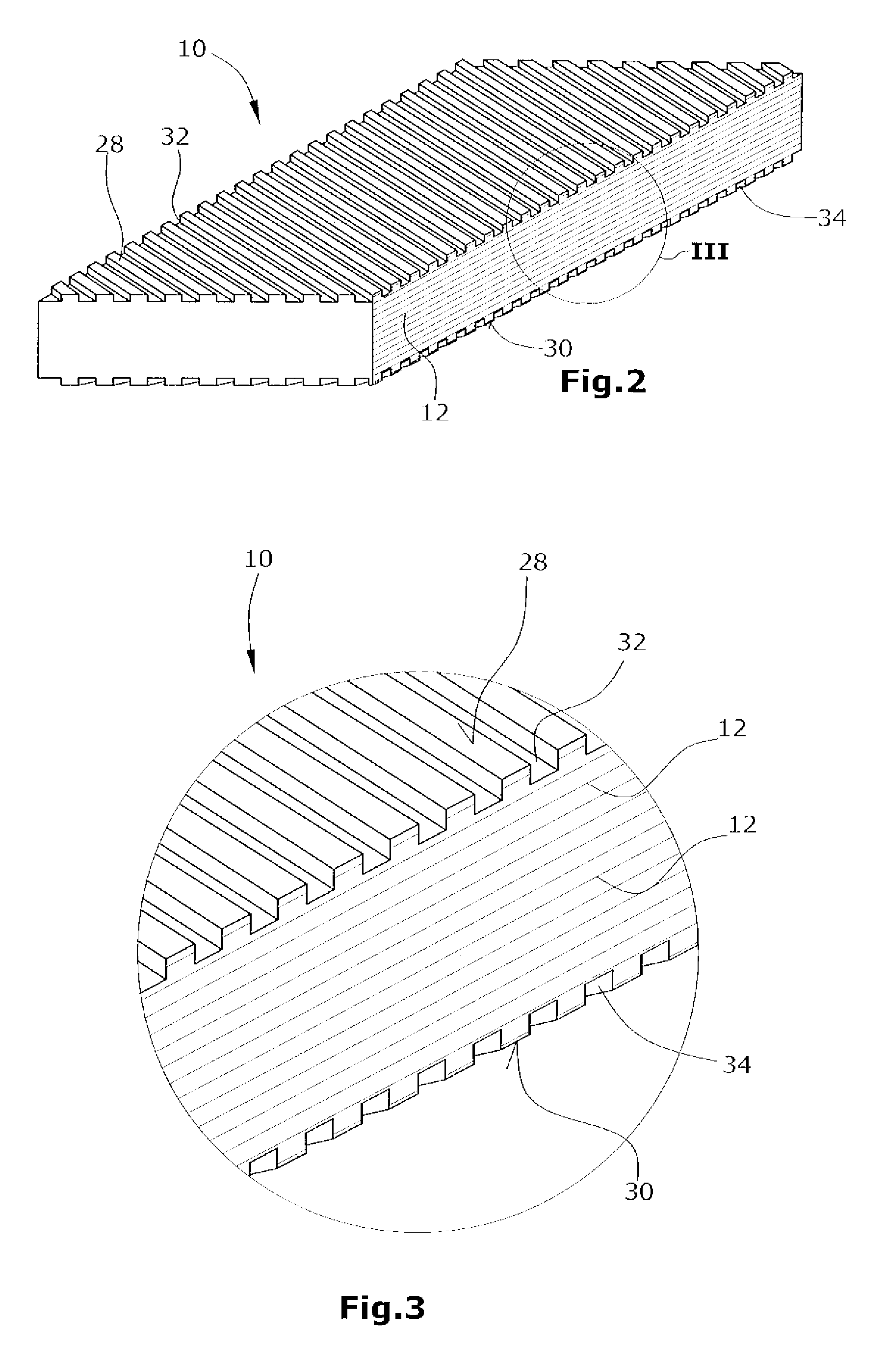
[0023]The composite of fibers 12 embedded in the epoxy resin is transported to a curing station 18. Thereafter, the cured laminate 20 is further transported to a channel forming station 22 comprising two grinding tools 24,26 for grinding the upper and lower major surfaces 28,30 of the cured laminate 20. In the channel forming station 22, by means of the upper and lower grinding tools 24,26 individual channels 32,34 are formed in the upper and lower major surfaces 28,30 of the cured laminate 20 in order to make the final prefabricated continuous fiber reinforced laminate 10 which thereafter is wound up as a coil 36. From this coil 36 several individual...


PUM

PropertyMeasurementUnit
thicknessaaaaaaaaaa
anglesaaaaaaaaaa
depthaaaaaaaaaa

Abstract

The method for making a continuous laminate, in particular suitable as a spar cap or another part of a wind energy turbine rotor blade comprises the steps of providing a plurality of parallel fibers, embedding the fibers in a curable matrix material, curing the matrix material so as to obtain a fiber reinforced laminate having upper and lower major surfaces, and forming channels into at least one of the upper and lower major surfaces of the laminate wherein the channels on the upper and / or lower major surfaces are angled with respect to the direction of the fibers.

Description

BACKGROUND[0001]1. Field of the Invention[0002]The present invention relates to a method for making a fiber reinforced endless or continuous laminate which can be used for manufacturing a spar cap or another part of a rotor blade of a wind energy turbine. Moreover, the present invention relates to the use of such a laminate for making structures such as a spar cap or another part of a rotor blade of a wind energy turbine.[0003]2. Related Prior Art[0004]Continuous laminates, i.e. endless flat panels of fiber-reinforced resin or other curable material are basically known. These laminates are produced in a continuous process by pulling tows of fibers (e.g. of glass or carbon) through a bath of resin and by forming the panel thus obtained. Within the laminates the fibers are arranged side by side and are aligned substantially parallel to each other. These continuous laminates can have a thickness between under 1 mm and up to several mm. The width of the laminate can be realised in subst...

Claims


Application Information

Patent Timeline
Patent Type & Authority Patents(United States)
IPC IPC(8): B32B38/14
CPCB29C70/525F03D1/065B29L2031/085F05B2230/20F05B2280/6003F05B2280/6013F05B2280/6014F05C2253/04F05C2253/16F05C2253/18Y02E10/721B29C70/545B29C2793/009B29C59/021B29C70/504B29C59/043B29C2793/0009Y02E10/72Y02P70/50
Inventor ARELT, RAINER
Owner LM WIND POWER US TECH APS
Learn More