Forward-looking sonar for ships and boats

a sonar and forward-looking technology, applied in the field of sonar systems, can solve the problems of inability to penetrate very far into sediment-laden water, fish finders, acoustic cameras and narrow-beam search devices operating at higher frequencies

Inactive Publication Date: 2012-06-19
HICKLING ROBERT
View PDF7 Cites 10 Cited by
  • Summary
  • Abstract
  • Description
  • Claims
  • Application Information

AI Technical Summary

Benefits of technology

[0011]A half-space vector probe detects sound from the forward half of the surrounding space. Behind the probe is a solid concave axisymmetric structure lined with sound-absorbing material that is open in the probe's forward direction. This prevents noise intrusion from behind the probe. The axis of the structure coincides with the central axis of the probe. The structure can be attached to a back-plate that supports the four hydrophones of the probe.

Problems solved by technology

Fish finders, acoustic cameras and narrow-beam search devices operate at higher frequencies and are incapable of penetrating very far in sediment-laden water.

Method used


Image

  • Forward-looking sonar for ships and boats
  • Forward-looking sonar for ships and boats
  • Forward-looking sonar for ships and boats

Examples


Embodiment Construction

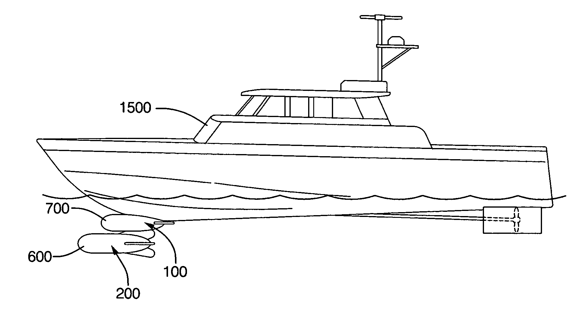
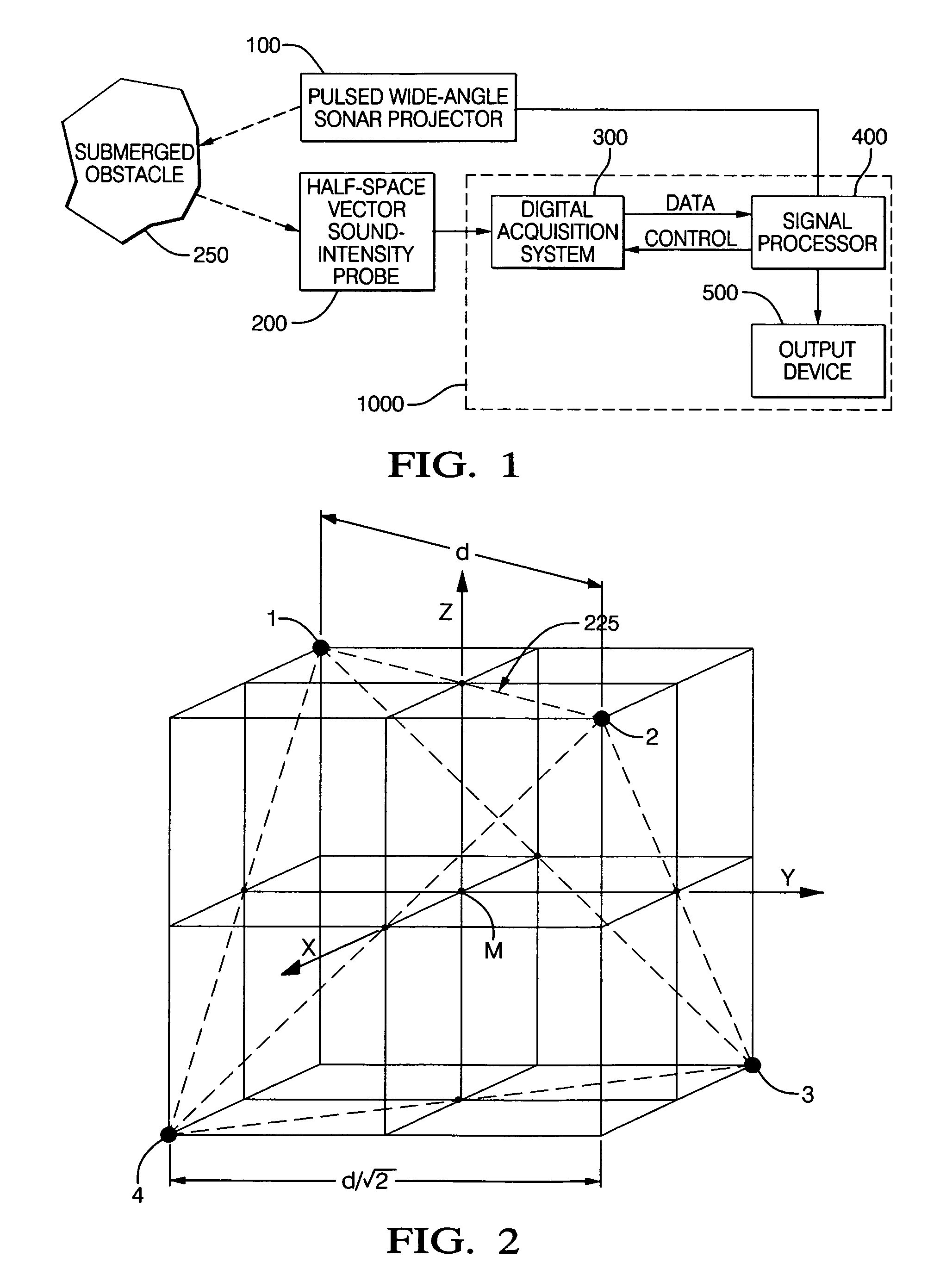
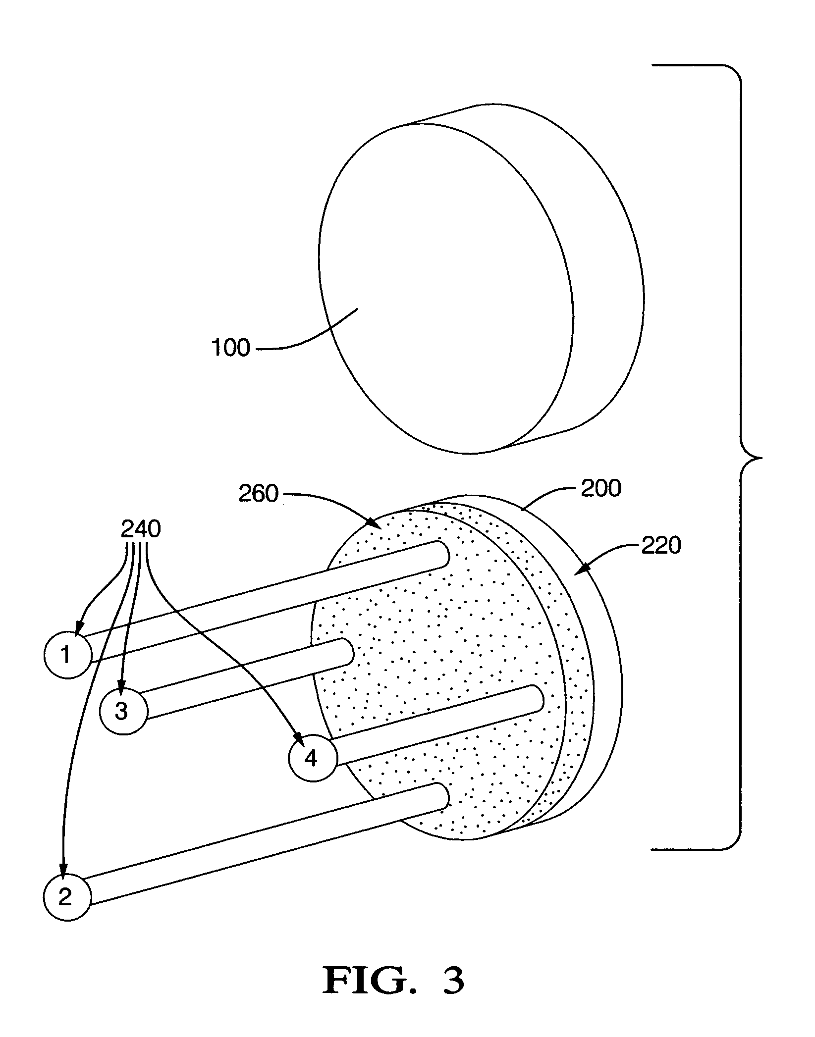
[0020]FIG. 1 is a block diagram showing the different components of the forward-looking sonar for ships and boats. A signal processor 400 drives a pulsed, wide-angle sonar projector 100. The projector 100 operates at frequencies of roughly 30 kHz and below, in order to penetrate sediment-laden water for distances of hundreds of meters or more. The projector 100 generates echo pulses from submerged obstacles 250 that are received by a half-space, vector sound-intensity probe 200. The probe 200 is linked, by means of a digital-acquisition system 300, to a digital signal processor 400. The signal processor 400 uses the echoes received by the probe 200 to detect and determine the location of submerged obstacles 250 ahead of the ship or boat. This information is displayed on an output device 500. The distance and direction of an object determine its location. Distance is calculated using time-of-flight and the sound-intensity vector determines direction. The sonar projector 100 and vecto...


PUM


Abstract

Method and apparatus for detecting and locating underwater obstacles in the path of a ship or boat. The apparatus includes a pulsed wide-angle sonar projector (100) controlled by a digital signal processor (400) that emits sound pulses at frequencies of 30 kHz and less that can penetrate sediment-laden water hundreds of meters or more ahead of the ship or boat. The projector generates echoes from submerged objects. A vector sound-intensity probe (200) receives the echoes and transmits them to the digital signal processor. The digital signal processor determines the location of submerged obstacles ahead of the ship or boat from the echoes received by the probe. This information is displayed on an output device (500). The sonar projector and vector sound-intensity probe are contained separately in streamlined housings aimed in the forward direction under the bow of the ship or boat. The processor, output device and other electronics are located on board the ship or boat.

Description

[0001]THIS APPLICATION IS A CONTINUATION-IN-PART OF U.S. patent application Ser. No. 10 / 396,541, filed Mar. 25, 2003, ENTITLED “ACOUSTIC MEASUREMENT METHOD AND APPARATUS”, U.S. Pat. No. 7,058,184, issued Jun. 6, 2006, OF U.S. patent application Ser. No. 10 / 746,763, filed Dec. 26, 2003, ENTITLED “SOUND SOURCE LOCATION AND QUANTIFICATION USING VECTOR PROBES” U.S. Pat. No. 7,054,228, issued May 30, 2006, OF U.S. patent application Ser. No. 10 / 842,880, filed May 10, 2004, ENTITLED[0002]“METHOD AND APPARATUS FOR ECHOLOCATION”, U.S. Pat. No. 7,054,226, issued May 30, 2006, OF CONTINUATION-IN-PART ENTITLED “VECTOR SOUND-INTENSITY PROBES OPERATING IN A HALF SPACE” Ser. No. 11 / 607,376 FILED 2006 Dec. 2 now U.S. Pat. No. 7,920,709. BY ROBERT HICKLING, THE PRESENT INVENTOR.TECHNICAL FIELD[0003]This invention relates to a sonar system at the bow of a ship or boat for detecting underwater obstacles.BACKGROUND OF THE INVENTION[0004]1. U.S. Pat. No. 7,054,226 May 30, 2006 issued to R. Hickling ent...

Claims


Application Information

Patent Timeline
Patent Type & Authority Patents(United States)
IPC IPC(8): G01S15/88
CPCG01N29/11G01N29/341G01N29/36G01S7/521G01S15/89G01S15/93G01N2291/02491G01N2291/02836G01N2291/044
Inventor HICKLING, ROBERT
Owner HICKLING ROBERT
Why Eureka
Try Eureka