
Test module for motor control center subunit

a test module and motor control technology, applied in the direction of electric power measurement, emergency protective arrangement for automatic disconnection, electric devices, etc., can solve the problems of difficult manual maneuverability of line connections or stabs, and the difficulty of monitoring conditions inside the buck

Active Publication Date: 2012-06-12
EATON INTELLIGENT POWER LTD
View PDF85 Cites 34 Cited by
  • Summary
  • Abstract
  • Description
  • Claims
  • Application Information

AI Technical Summary

Benefits of technology

The present invention provides a system and method for installing a motor control center subunit and connecting motor control components to a power supply. The system uses moveable line stabs to contain potential arc flashes and interlocks to ensure safe installation and removal of the bucket. A test module is included to indicate the operation characteristics of the motor control center subunit after installation. The invention also includes a base module that allows users to determine the internal condition of the subunit, and a method of manufacturing the base module. The technical effects of the invention include improved safety and reliability of the motor control center subunit, as well as improved operational efficiency and convenience for users.

Problems solved by technology

The line connections or stabs may be difficult to maneuver manually when an operator is supporting the entire bucket or when the stabs are not visible.
However, many of these systems require that the bucket or compartment door be open to manipulate the handles and line stabs.
Similarly, once a bucket has been fully installed and / or sealed in place in a motor control center, it becomes difficult to monitor conditions inside the bucket without disconnecting the bucket and removing it from the motor control center.

Method used


Image

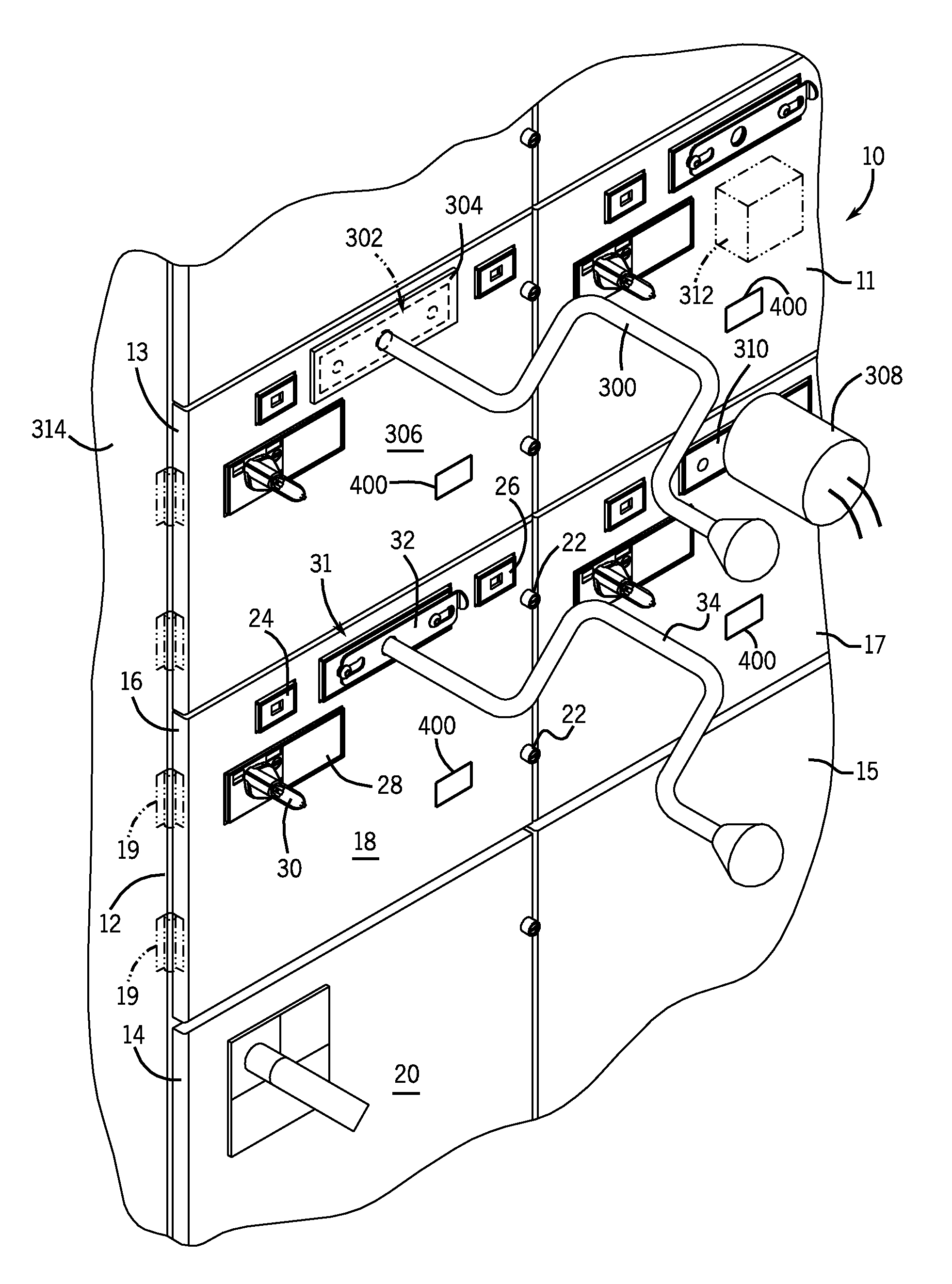
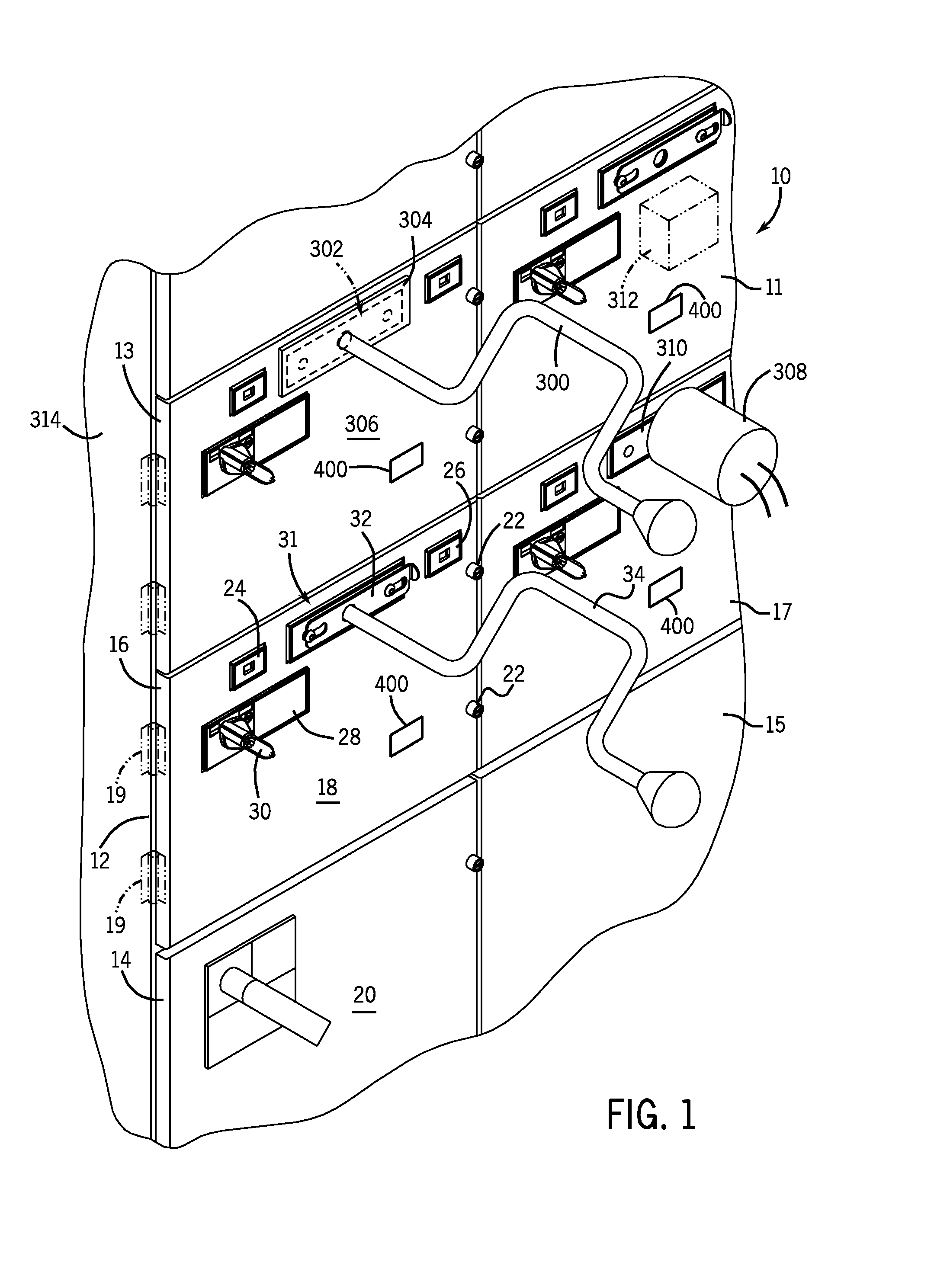
  • Test module for motor control center subunit
  • Test module for motor control center subunit
  • Test module for motor control center subunit

Examples


Embodiment Construction

[0042]The following description makes reference to supply power, supply power lines, motor power, load power, line power, and the like. It is appreciated that such terms may refer to a variety of both common and uniquely conditioned voltage and current characteristics, including but not limited to, three phase AC power, single phase AC power, DC power, multiple DC power lines, or any combination thereof. Such power characteristics will be generally referred to as being provided on a bus, supply line, or riser of a motor control center. However, it is appreciated that the present invention may find applicability in other power connectivity configurations, adapted or apart from motor control centers. An example of supply power commonly used in motor control centers is 480V three-phase AC power distributed over three separate supply bus bars. In addition, references to “motor control components” shall be understood to include the various types of devices and control components which ma...


PUM

PropertyMeasurementUnit
distancesaaaaaaaaaa
electrical conditionaaaaaaaaaa
internal electrical conditionaaaaaaaaaa

Abstract

A system and method are provided for coordinating the installation and removal a motor control center subunit with the power connection and interruption thereof. A system of interlocks and indicators causes an operator to install a motor control center subunit into a motor control center, and connect supply and control power thereto, in a particular order. Once installed, a test module system included with the subunit provides for pass-through connection of signals from equipment test points. The test module can thus relay internal conditions of the subunit to the operator without a need for disengaging or opening the subunit.

Description

CROSS-REFERENCE TO RELATED APPLICATIONS[0001]The present application claims the benefit of U.S. provisional application Ser. No. 60 / 891,831, filed on Feb. 27, 2007, the disclosure of which is incorporated herein by reference.BACKGROUND OF THE INVENTION[0002]The present invention relates generally to a system and method for motor control, and more particularly, to a test module for use with a subunit for a motor control center. The test module provides equipment connection points and voltage test points, so that a user can monitor internal conditions of the subunit when the subunit is installed into the motor control center. In one embodiment, the system and method described herein provide for connection of external accessories, such as motor meggaring devices, voltage / current testing equipment, and motor wellness units, to internal test points of the subunit, without a need for removing or opening the motor control center subunit.[0003]A motor control center is a multi-compartment s...

Claims


Application Information

Patent Timeline
Patent Type & Authority Patents(United States)
IPC IPC(8): B60Q1/00H02B5/00G08B1/08H04Q5/22G01R15/00
CPCG01R1/04H02B1/21Y10T29/49002H02B1/36H02B11/24
Inventor MORRIS, ROBERT A.MCPHERREN, SCOTT E.YEE, EDGAR
Owner EATON INTELLIGENT POWER LTD
Learn More