Engine start-up device for hybrid vehicle power transmitting device

a technology of power transmission device and hybrid vehicle, which is applied in the direction of mechanical equipment, electric propulsion mounting, transportation and packaging, etc., can solve the problems of delay in engine completion, driver's perception of delay in drive torque, and the likelihood of difficulty in rapid so as to increase accelerate the response. , the effect of increasing the rotation speed of the engin

Active Publication Date: 2012-06-12
TOYOTA JIDOSHA KK
View PDF21 Cites 2 Cited by
  • Summary
  • Abstract
  • Description
  • Claims
  • Application Information

AI Technical Summary

Benefits of technology

[0035]With the first aspect of the invention, the starting up method the engine for the shifting of the shifting portion is altered relative to the starting up method the engine for the non-shifting of the shifting portion. This can prevent an operation to start-up the engine from adversely affecting the shifting of the shifting portion. In addition, due to a capability of beginning the operation to start-up the engine during the shifting of the shifting portion, such an operation is commenced after the shifting has been completed. In such a case, the shifting portion can have quicker response in acceleration at a request of a driver than that achieved in a case where such an operation and the shifting are not concurrently executed.
[0036]Further, preferably, the shifting portion may include a step-variable type transmission. More preferably, as used herein, the term “method of starting up an engine” may refer to a method of increasing a rotation speed of the engine for starting up the engine.
[0037]With the second aspect of the invention, during the non-shifting of the shifting portion, the rotation speed of the engine for start-up thereof is caused to increase by using either one of the first and second electric motors. This allows the control to be executed for increasing the rotation speed of the engine on an easier stage than that in which the control is executed when using both of the first and second electric motors, enabling a reduction in control load of the control device during the non-shifting of the shifting portion.
[0038]With the third aspect of the invention, during the shifting of the shifting portion, the rotation speed of the engine for start-up thereof is caused to increase upon using both the first and second electric motors. This can increase the rotation speed of the engine for start-up thereof during the shifting of the shifting portion. This result in starting up the engine on an earlier stage to provide improved response on the acceleration required by the driver. Meanwhile, during the non-shifting of the shifting portion, using either of one of the first and second electric motors enables an increase in the rotation speed of the engine for start-up thereof, enabling a reduction in control load of the control device during the non-shifting of the shifting portion.
[0039]More preferably, during the motor drive mode in which no output is generated from the engine and the second electric motor is used as a drive power source to run a hybrid vehicle, the rotation speed of the engine for start-up thereof can be caused to increase.
[0040]More preferably, when increasing the rotation speed of the engine for start-up thereof using both the first and second electric motors, the first and second electric motors are caused to rotate in a common direction in which the engine is caused to rotate.

Problems solved by technology

Therefore, if there is a request for executing the shifting in response to a manipulation of a driver during a start-up control of the engine, the completion of the shifting is delayed with respect to the request on the shifting, with accompanying consequence of causing the driver to feel an increase delay in drive torque.
Thus, there was a likelihood of a difficulty being encountered in rapidly increasing the rotation speed of the engine.

Method used


Image

  • Engine start-up device for hybrid vehicle power transmitting device
  • Engine start-up device for hybrid vehicle power transmitting device
  • Engine start-up device for hybrid vehicle power transmitting device

Examples


first embodiment

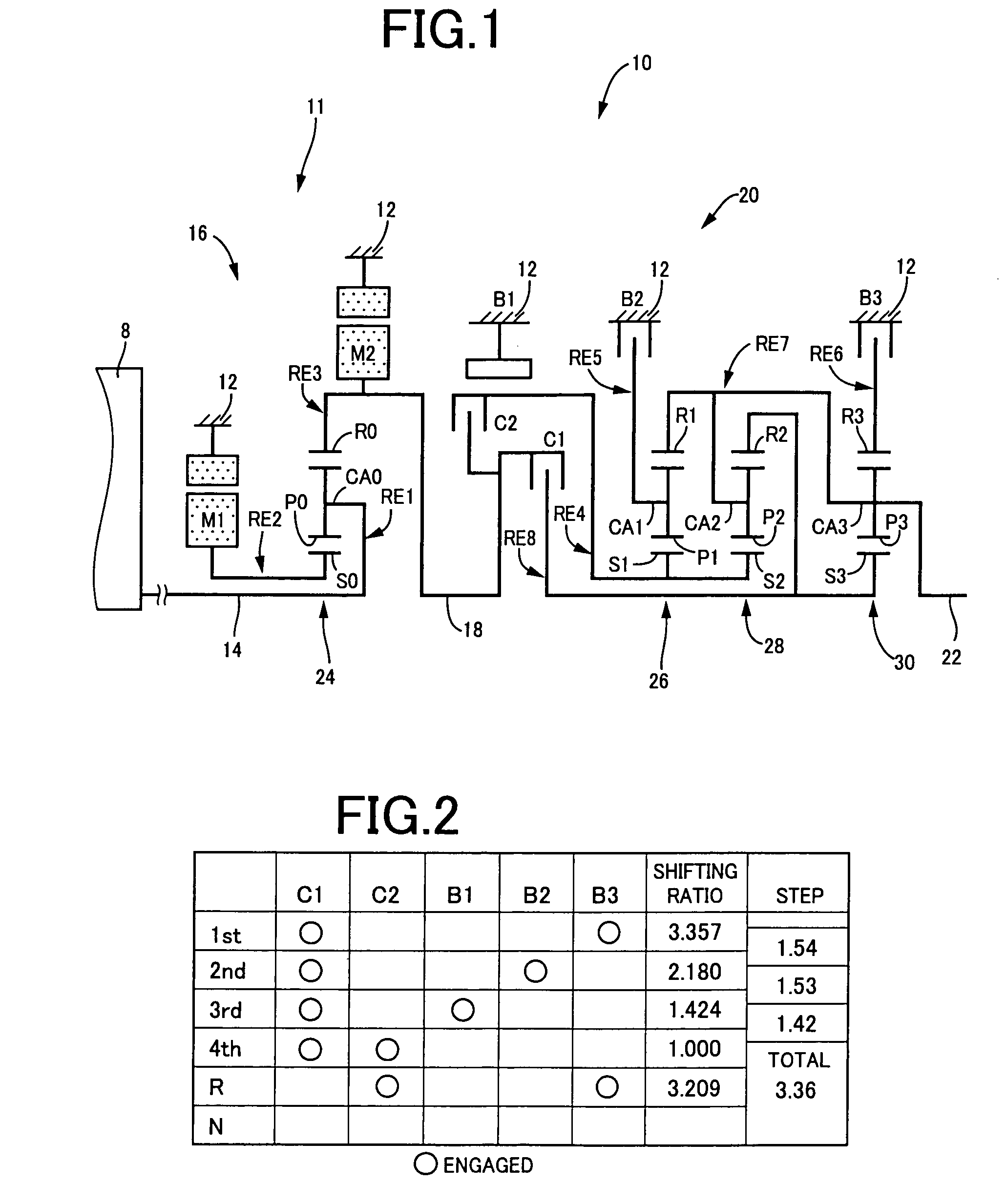
[0090]FIG. 1 is a skeleton diagram for illustrating a transmission mechanism i.e., shifting mechanism 10 constituting a part of a hybrid vehicle power transmitting device to which the present invention is applied. As shown in FIG. 1, the transmission mechanism 10 includes a transmission case 12 (hereinafter referred to as “a case 12”) mounted on a vehicle body as a non-rotary member, an input shaft 14 disposed inside the case 12 as an input rotary member, a differential portion 11 coaxially connected to the input shaft 14 either directly, or indirectly via a pulsation absorbing damper (vibration damping device), not shown, and serving as a continuously variable transmission portion, an automatic transmission portion 20 connected in series in a power transmitting path between the differential portion 11 and drive wheels 34 (see FIG. 6) through a power transmitting member 18 (power transmitting shaft), and an output shaft 22 connected to the automatic transmission portion 20 and servi...

second embodiment

[0197]A second embodiment, described below, is identical in part to the first embodiment in respect of FIG. 1 and FIGS. 5 and 7 and FIG. 6 (corresponding to FIG. 12 for the second embodiment). Therefore, for the sake of simplified description, descriptions on and illustrations of these drawings will be omitted herein but will be referred to those descriptions and illustrations when needed. A control device of the second embodiment is shown in FIG. 4 in the form of “control device 110”. Hereunder, the second embodiment will be described below with a focus on points different from the first embodiment in structure and operation thereof.

[0198]With the second embodiment, the first and second electric motors M1 and M2 incorporate therein rotation speed sensors such as resolvers, respectively, each for enabling the detection of a rotation speed and a rotational direction.

[0199]Considering response and comfort demanded by a driver, when a running state of a vehicle changes from a motor dri...

third embodiment

[0246]A third embodiment takes the form of a structure wherein the electronic control device 110 of the second embodiment is replaced by an electronic control device 130. The third embodiment has the structure including engine start-up control means 162, provided in place of the engine start-up control means 146 in the functional block diagram shown in FIG. 12 related to the second embodiment, and the other same component parts, such as the engine start-up determining means 140, the shifting state determining means 142, the motor limited state determining means 144 and the shifting control altering means 148, as those of the second embodiment shown in FIG. 12. Hereunder, description will be given of the third embodiment with a focus on differing points.

[0247]The engine start-up determining means 140 determines that the engine start-up determination is made and the shifting state determining means 142 makes a determination affirming that the shifting is executed in the automatic shif...


PUM


Abstract

With an engine start-up device, an engine is started upon altering a start-up when shifting an automatic shifting portion relative to when the automatic shifting portion is not shifting. Thus, start-up of the engine is prevented from adversely affecting the shifting of the automatic shifting portion. The engine starts during the shifting of the automatic shifting portion, enabling further improved response in acceleration required by a driver than that achieved when the operation is commenced after the automatic shifting portion has completed the shifting.

Description

BACKGROUND OF THE INVENTION[0001]1. Field of the Invention[0002]This invention relates to control devices for hybrid vehicle power transmitting devices. More particularly, it relates to a hybrid vehicle power transmitting device, including an engine, composed of an internal combustion engine serving as a drive power source to run a vehicle, and an electric motor, and a technology of starting up the engine during a switchover from a motor drive mode to an engine drive mode.[0003]2. Description of the Related Art[0004]In the related art, there has been known a hybrid vehicle drive device wherein drive torque, delivered from a main power source composed of an engine, a first electric motor and a differential mechanism, is transferred to drive wheels through an output shaft to which a second electric motor is connected via an automatic transmission. With such a hybrid vehicle drive device, a control device has heretofore been known in which a vehicle occupant is prevented from suffering...

Claims


Application Information

Patent Timeline
Patent Type & Authority Patents(United States)
IPC IPC(8): B60K1/02B60W10/10B60W30/18
CPCB60K6/445B60W10/06B60W10/08B60W10/115B60W30/18018Y10T477/23Y02T10/6286Y02T10/48Y02T10/6239B60W20/00Y02T10/40Y02T10/62B60K2006/268B60W10/02B60W2710/02
Inventor SHIBATA, HIROYUKITABATA, ATSUSHIMATSUBARA, TOORUKUMAZAKI, KENTA
Owner TOYOTA JIDOSHA KK
Why Eureka
Try Eureka