Folding container

a container and container body technology, applied in the field of folding containers, can solve the problems of inconceivable quantity of goods exchanged between far east, south america, the european continent and russia, friction always occurs, and more energy is also required, so as to facilitate the folding process, and facilitate the effect of folding

Inactive Publication Date: 2012-06-12
TEXAS OIL CAPITAL HLDG CORP
View PDF12 Cites 17 Cited by
  • Summary
  • Abstract
  • Description
  • Claims
  • Application Information

AI Technical Summary

Benefits of technology

[0014]The advantage of the invention consists in that with the tension springs an instrument that is easy to handle is available with which friction forces that occur during the rolling movement in the longitudinal rails can be effectively offset.
[0015]An advantageous embodiment of the invention provides that the face and back end is in the form of roll-up doors. The roll-up doors are embodied in lightweight construction for example as composite materials and are segmented in order to be able to follow the radial guide integrated in a roof. In vertical direction the roll-up doors are guided through the guides fastened to the lateral parts. To ensure these are waterproof, each lowermost segment of the roll-up doors is embodied with a rubber seal. Locking in the closed state is carried out with the help of commercially available locking elements.
[0016]Further advantageous embodiments of the invention are characterized in the subclaims.

Problems solved by technology

Without container transport, the quantities of goods exchanged between Far East, South America, the European Continent and Russia would be inconceivable.
However, friction always occurs, also with the known folding containers.
The occurrence of friction manifestations constitutes a problem with the known folding containers in that increased force has to be expended as a result and consequently more energies are also required in order to fold and unfold the container.
Friction losses between guide roll and guide rails also slow down the folding operation.

Method used


Image

  • Folding container
  • Folding container
  • Folding container

Examples


Embodiment Construction

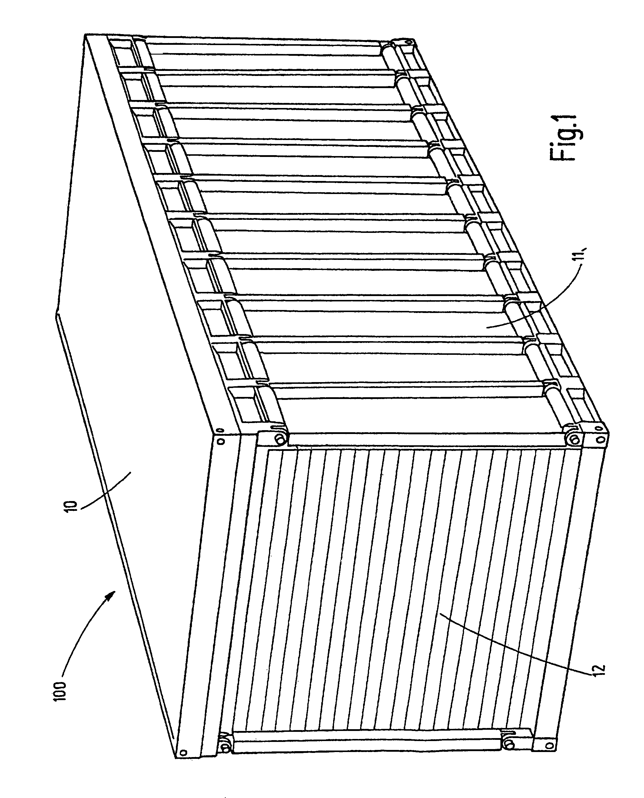
[0025]FIG. 1 shows a folding container according to the invention which is given the reference symbol 100.

[0026]The walling of the folding container 100, the face end 12 and the back end, the side walls 11, 13 and the roof 10 consists of a composite material which is characterized by low weight.

[0027]At the corner points, an eye plate or an eye each is worked into the roof 10 in order to lift the container 100 with a conventional lifting device in such a manner that it is released from an anchorage in the floor 20 and the roll guides are thus activated.

[0028]The folding container 100 comprises a first side wall 13 (see FIG. 2) and a second side wall 11, a roof 10, a floor 20 (see FIG. 2) and a face end 12 and a back end. Both the face end 12 as well as the back end can be present in the form of roll-up doors.

[0029]FIG. 2 shows the roll container according to the invention with an opened face end 12. The floor 20 consists of a strong steel frame, a steel floor plate as well as cross ...


PUM


Abstract

The invention relates to a folding container (100) having a first and second side wall (11, 13), a roof (10), a floor (20) as well as a face end (12) and a back end, wherein the first side wall (13) and the second side wall (11) are slideable along the roof (10) and along the floor (20) respectively in such a manner that the lateral parts (11, 13) are slideable inward of the container (100) until they lie parallel to the floor (20). In order to offset friction losses in the longitudinal rails of folding containers (100), the invention proposes that the roof (10) and the floor (20) are provided with spaced longitudinal rails (14, 15, 16, 17) running parallel to one another for a roll guide of the first side wall (13) slideable on the roof (10) and for a roll guide of the second side wall (11) slideable on the floor (20), wherein in the longitudinal rails (14, 15, 16, 17) tension springs (30) are integrated which with a folded-out container (100) are tensioned and with a folded-up container (100) are relaxed.

Description

[0001]This application claims priority from PCT International application PCT / DE2007 / 001718 (filed Feb. 28, 2007), and the contents of this priority application is incorporated in its entirety by reference.TECHNICAL AREA[0002]The invention relates to a folding container having a first and second side wall, a roof, a floor as well as a face end and a back end, wherein the first side wall and the second side wall are slideable along the roof and along the floor respectively in such a manner that the lateral parts are slideable inwards of the container until they lie parallel with the floor.PRIOR ART[0003]Folding containers of the type mentioned at the outset are known and familiar to the person skilled in the art.[0004]In general container traffic both by sea, on the road and on rail has gained increasing importance in recent years. The growth forecasts of sea traffic for example are based on the sustained growth of the world population (1.1 billion humans in the next 15 years), and t...

Claims


Application Information

Patent Timeline
Patent Type & Authority Patents(United States)
IPC IPC(8): B65D6/00B65D88/00B65D8/14B65D21/00B65D85/62
CPCB65D88/52B65D88/522B65D90/0086B65D90/021B65D88/121
Inventor SCHRAYVOGEL, OTTMAR A. H.
Owner TEXAS OIL CAPITAL HLDG CORP
Why Eureka
Try Eureka