
Mobile robot

a mobile robot and robot technology, applied in the field of mobile robots, can solve the problems of limitation in the use of conventional mobile robots, inability to effectively move in poor ground conditions, etc., and achieve the effect of more effective realization of the jumping function

Inactive Publication Date: 2012-05-29
CONVEX
View PDF14 Cites 36 Cited by
  • Summary
  • Abstract
  • Description
  • Claims
  • Application Information

AI Technical Summary

Benefits of technology

[0012]According to the present invention, the leaf spring is provided to the robot body of the mobile robot and the leaf spring control unit for bending and then unbending the leaf spring is provided, so the mobile robot can jump using the force of restitution of the bent leaf spring.
[0013]Further, the leaf spring control unit provides force for bending the leaf spring and at the same time the leaf spring is allowed to return its original position without load by the force of restitution thereof, so the mobile robot can jump using the force generated by allowing the leaf spring to push the ground.
[0014]Still further, with the help of the clutch mechanism which selectively allows the bent leaf spring to return to its original position, jump function can be more effectively realized.
[0015]In addition, the rotation position control unit for rotating the inverted robot body in a state that the leaf spring is bent is provided, so direction of jump of the mobile robot can be controlled.

Problems solved by technology

A robot should be able to move in various ground conditions having obstacles to perform guard or scouting mission, but there is a problem that the conventional mobile robot cannot effectively move in poor ground conditions.
In addition, the conventional mobile robot does not have a jump function, so there is limitation in use of the conventional mobile robot.

Method used


Image

  • Mobile robot
  • Mobile robot
  • Mobile robot

Examples


Embodiment Construction

[0039]Hereinafter, embodiments of the present invention will be explained with reference to the drawings.

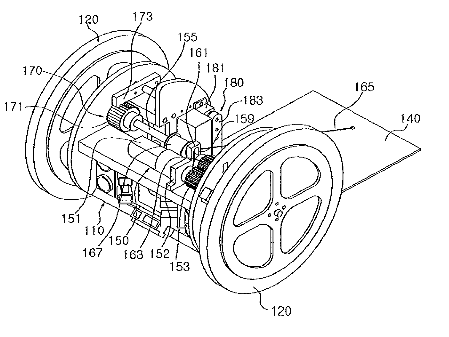
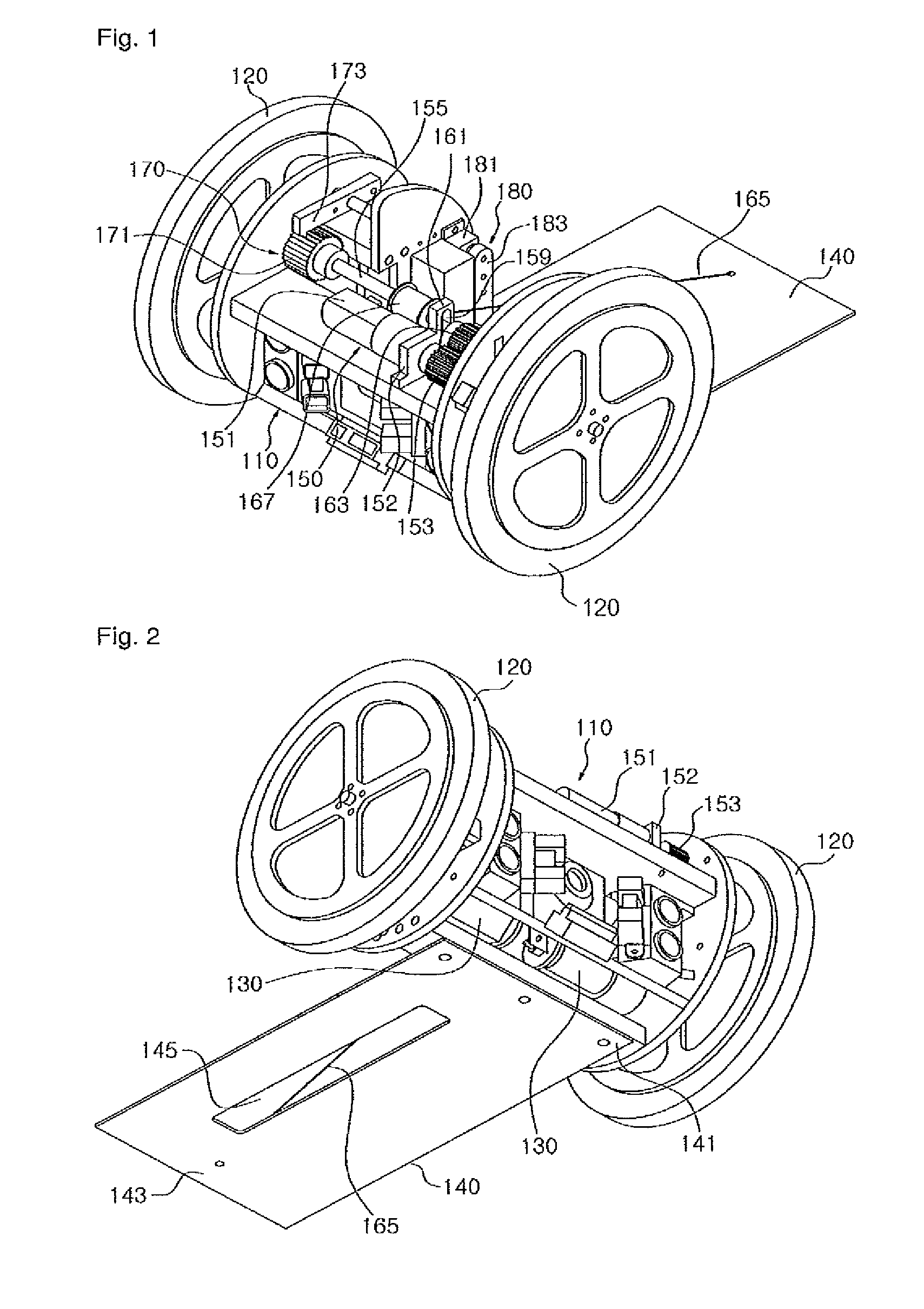
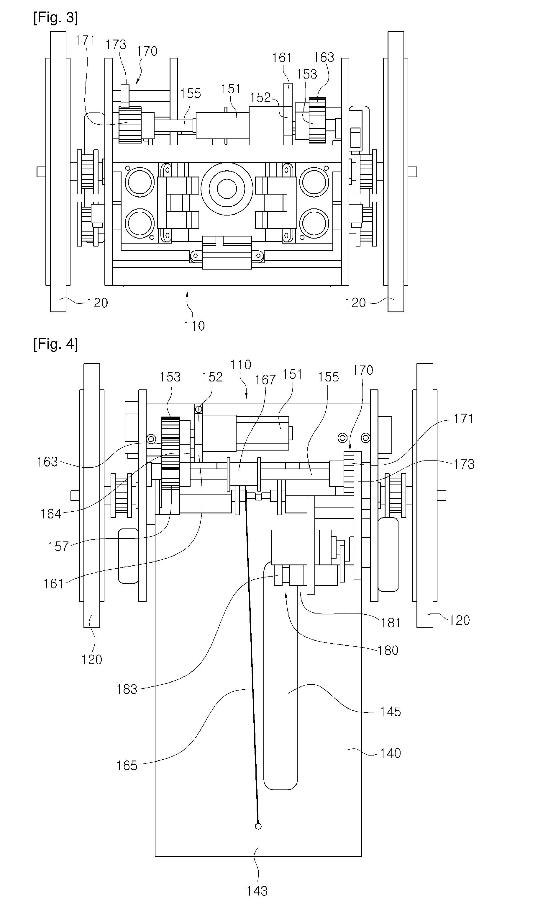
[0040]FIG. 1 is a perspective view of a mobile robot according to an embodiment of the present invention, FIG. 2 is a bottom perspective view of a mobile robot according to an embodiment of the present invention, FIG. 3 is a front view of a mobile robot according to an embodiment of the present invention, and FIG. 4 is a top plan view of a mobile robot according to an embodiment of the present invention.

[0041]Referring to FIG. 1 to FIG. 4, a mobile robot according to an embodiment of the present invention includes a robot body 110. The robot body 110 serves as a frame to which various elements of a mobile robot are mounted and may be formed as a plurality of supporting plates and supporting structures.

[0042]A pair of wheels 120 are rotatably connected to the robot body 110. For example, as shown in the drawing, the wheels 120 are connected to both sides of the robot body 110 to f...


PUM


Abstract

The present invention relates to a mobile robot having jump function. An exemplary mobile robot according to an embodiment of the present invention includes a robot body, a pair of wheels, a driving motor, a leaf spring, and a leaf spring control unit. The pair of wheels are rotatably connected to the robot body. The driving motor drives the pair of wheels so as to move the robot body. The leaf spring has a fixed end fixedly connected to the robot body and a free end disposed to face the fixed end in a state of being apart from the robot body. The leaf spring control unit applies force for bending the leaf spring such that the free end of the leaf spring is pulled toward the robot body and then removes the force applied to the leaf spring such that the leaf spring returns to an original state.

Description

TECHNICAL FIELD[0001]The present invention relates to a mobile robot. More particularly, the present invention relates to a mobile robot having a jump function.BACKGROUND ART[0002]With developments in robot technology, a mobile robot has been introduced, and a mobile robot may be applied in various fields. For example, various robots such as a cleaning robot, a surveillance robot, or other types of robots are developed.[0003]In particular, a robot for performing missions such as guard and scouting has an advantage to be able to be placed in poor surroundings where it is difficult for a person to perform guard or scouting mission and to effectively perform various missions there.[0004]A robot should be able to move in various ground conditions having obstacles to perform guard or scouting mission, but there is a problem that the conventional mobile robot cannot effectively move in poor ground conditions. In addition, the conventional mobile robot does not have a jump function, so the...

Claims


Application Information

Patent Timeline
Patent Type & Authority Patents(United States)
IPC IPC(8): B62D11/00
CPCB25J5/007B25J9/102B25J13/089Y10S901/01
Inventor YIM, CHOONG-HYUKKIM, DONG-HWAN
Owner CONVEX
Learn More