Electrical connector
a technology of electrical connectors and connectors, applied in the direction of fixed connections, electrical discharge lamps, coupling device connections, etc., can solve the problems of poor electrical connection at the soldered portion and poor electrical conduction at the corresponding circuit portion
- Summary
- Abstract
- Description
- Claims
- Application Information
AI Technical Summary
Benefits of technology
Problems solved by technology
Method used
Image
Examples
first embodiment
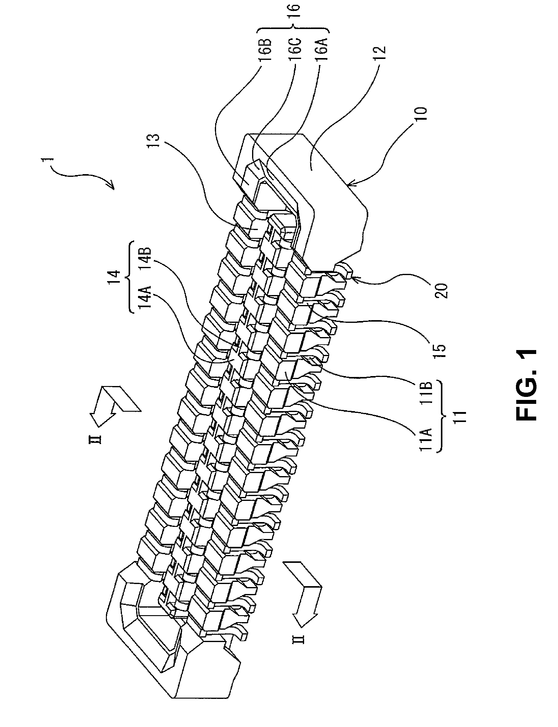
[0036]FIG. 1 is a perspective view showing an electrical connector 1 (a connector 1) for a circuit board according to an embodiment of the present invention. FIGS. 2(A) and 2(B) show an assembling process of the connector 1, wherein FIG. 2(A) shows a state that a terminal 20 is in a halfway of being attached to a housing 10, and FIG. 2(B) shows a state the terminal 20 is completely attached to the housing 10. FIGS. 2(A) and 2(B) are sectional views taken along a line II-II in FIG. 1, that is, where the terminal 20 is situated in a longitudinal direction of the housing 10.
[0037]As shown in FIG. 1, the connector 1 according to the embodiment of the present invention is to be attached to the circuit board (not shown). The connector 1 includes the housing 10 made of a synthetic resin and a plurality of the terminals 20 made of a metal plate disposed and held in the housing 10.
[0038]The housing 10 includes a receiving recess portion 13 opening in an upper direction. The connector 1 recei...
second embodiment
[0079]In the connector according to a second embodiment, the locking portion of the engaging arm portion of the terminal does not have a protruding shape while the connector in the first embodiment has the locking portion with the protruding shape in the engaging arm portion. The connector according to the embodiment has the same configuration with the connector according to the first embodiment as a basic structure. Accordingly, the components in the embodiment will be given reference numerals adding 100 to the reference numerals of the same components in the first embodiment respectively, and the explanation thereof will be omitted. Differences from the first embodiment will be mainly explained.
[0080]FIG. 5 is a sectional view showing a connector 101 according to the embodiment. As shown in FIG. 5, an engaging arm portion 121B includes an edge portion facing an inner surface of a secondary side wall portion 111B (an outside surface of a receiving recess portion 113) and extending ...
third embodiment
[0081]In the connector according to a third embodiment, the locking portion of the engaging arm portion of the terminal does not have a protruding shape while the connector in the first embodiment has the locking portion with the protruding shape of the engaging arm portion. The connector according to the embodiment has the same configuration with the connector according to the first embodiment as a basic structure. Accordingly, the components in the embodiment will be given reference numerals adding 200 to the reference numerals of the same components in the first embodiment respectively, and the explanation thereof will be omitted. Differences from the first embodiment will be mainly explained.
[0082]FIG. 6 is a sectional view showing a connector 201 according to the embodiment. As shown in FIG. 6, a contact arm portion 221A includes an edge portion facing a wall surface of a secondary central wall portion 214B (an inside surface of a receiving recess portion 213) and extending in ...
PUM
 Abstract
Description
Claims
Application Information
 - R&D
- Intellectual Property
- Life Sciences
- Materials
- Tech Scout
- Unparalleled Data Quality
- Higher Quality Content
- 60% Fewer Hallucinations
Browse by: Latest US Patents, China's latest patents, Technical Efficacy Thesaurus, Application Domain, Technology Topic, Popular Technical Reports.
© 2025 PatSnap. All rights reserved.Legal|Privacy policy|Modern Slavery Act Transparency Statement|Sitemap|About US| Contact US: help@patsnap.com


