
External safety illumination for a bus with light mounted to mirror arm

a safety illumination and bus technology, applied in the direction of vehicle components, signalling/lighting devices, optical viewing, etc., can solve the problems of not being able to safely move the vehicle, the driver's visibility around and behind the school bus is more difficult, and children may not be aware of the urgency

Active Publication Date: 2012-05-22
ROSCO
View PDF27 Cites 20 Cited by
  • Summary
  • Abstract
  • Description
  • Claims
  • Application Information

AI Technical Summary

Benefits of technology

The present invention provides an illumination system for school buses to improve safety and visibility. The system includes strip lighting along the side of the bus and down pointing floodlights on the roof or near the top of the bus. The lights can be triggered by an opening of the school bus door or a flashing light. The system also includes a control mode to turn off the lights after a set period of time. The lights can display letters or reflect the area around the bus to advise passengers of the vehicle's approach or safety. The system also includes a mirror mounting arm with down pointing light sources to illuminate the area near the school bus. The down pointing light sources can be fixed, sweep the area, or be controlled by the school bus operator. The system can improve safety and visibility for drivers and passengers.

Problems solved by technology

Passengers exiting and boarding or in the vicinity of a large vehicle, such as a truck, bus and / or school bus present the operator of the vehicle, such as the school bus driver, with the problem that the vehicle cannot be safely moved until the people in the vicinity and / or passengers have cleared the area around the vehicle.
School buses pose a particular challenge because they carry children and society has set higher standards for protecting these children, as they board and disembark from school buses.
Children are typically shorter than adults and therefore their visibility around and behind the school bus is more challenging for the school bus driver.
Also, children may not be aware of the urgency of the need to clear the area around the school bus.
However, poor visibility conditions, such as when it is dark or near dark outside or during misty or foggy conditions, present a problem for the school bus driver, even with the best mirror system and with the optimal camera system.

Method used


Image

  • External safety illumination for a bus with light mounted to mirror arm
  • External safety illumination for a bus with light mounted to mirror arm
  • External safety illumination for a bus with light mounted to mirror arm

Examples


Embodiment Construction

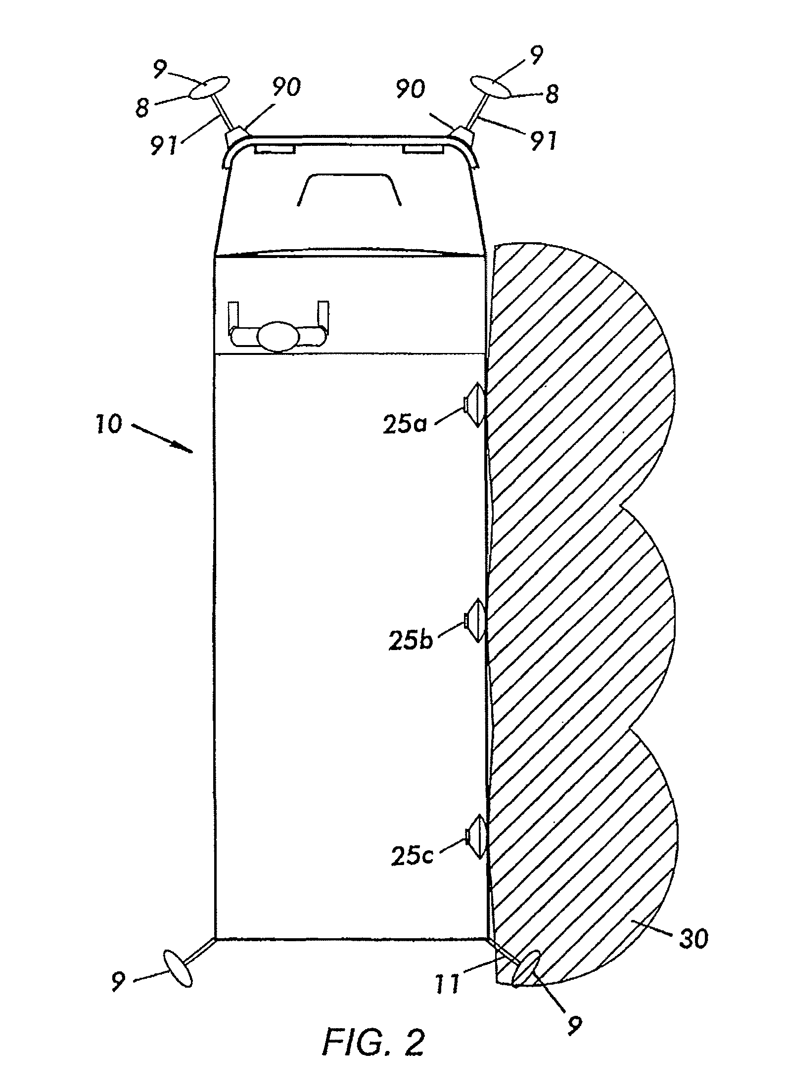
[0044]FIG. 1 shows a large vehicle, such as school bus 10 with illuminated areas 30 provided by, for example, lighting strips 20 mounted on both sides of the school bus 10, according to an embodiment of the present invention. Such illumination may be quite helpful to a vehicle operator, such as the school bus driver in preventing accidents involving passengers boarding or exiting from the vehicle. For example, during times of poor visibility when it is dark outside, such as at night, twilight, late winter afternoons, etc., children who are waiting to board the school bus 10 may linger or fall near the school bus 10 and accidentally end up near or underneath the school bus 10, as it starts moving. The illumination shown in FIG. 1 aids the school bus driver in spotting children or fallen objects underneath or near the school bus 10.

[0045]FIG. 2 shows an embodiment in which floodlights 25a, 25b and 25c are provided at or near the top of the school bus 10. The floodlights 25a-25c are fo...


PUM


Abstract

A light source along the mirror mounting arm of a school bus or other passenger vehicle to reduce the risk of people or other objects being injured by the school bus. The light source may be mounted directly on the mirror mounting arm or embedded within a mirror mount. The light source may be focused downward to illuminate the ground and may provide vehicle status information and guiding information. Additionally the light source may sweep the ground back and forth or be directed under the control of the driver. The light source may be activated automatically when movement is detected near the vehicle.

Description

CROSS REFERENCE TO RELATED APPLICATIONS[0001]The present application claims priority to U.S. Provisional Pat. App. No. 61 / 119,264, filed on Dec. 2, 2008 entitled EXTERNAL SAFETY ILLUMINATION FOR A BUS WITH LIGHT MOUNTED TO BRACKET. The present application is also a continuation-in-part of U.S. non-provisional patent application Ser. No. 11 / 936,522, filed on Nov. 7, 2007 entitled EXTERNAL SAFETY ILLUMINATION FOR A BUS, which claims priority to U.S. Provisional Application Ser. No. 60 / 913,580 filed Apr. 24, 2007 entitled EXTERNAL SAFETY ILLUMINATION FOR A BUS, and to U.S. Provisional Patent Application Ser. No. 60 / 857,250 filed Nov. 7, 2006 entitled MULTIPLE CAMERA SYSTEM FOR PROVIDING 360 DEGREE COVERAGE FOR SCHOOL BUSES, the entire contents of which applications are hereby incorporated by reference herein.FIELD OF THE INVENTION[0002]The present application generally relates to vehicle exterior illumination, and more particularly, to an illumination apparatus, system and method for i...

Claims


Application Information

Patent Timeline
Patent Type & Authority Patents(United States)
IPC IPC(8): B60Q1/26B60R1/12
CPCB60Q1/24B60Q1/323B60Q1/50B60Q1/2692B60Q1/2657B60Q1/247B60Q1/324B60Q1/5035B60Q1/543B60Q1/547
Inventor ENGLANDER, BENJAMINSERER, JULIANMCDONALD, DAVID
Owner ROSCO
Learn More