Image projection device including determining displayable region
a projection device and image technology, applied in the field of image projection apparatus, can solve the problems of difficult mounting of large-sized displays, increased power consumption, and eye stimulation of projection light, and achieve the effects of reducing the number of parts, reducing the cost, and reducing the size of the apparatus
- Summary
- Abstract
- Description
- Claims
- Application Information
AI Technical Summary
Benefits of technology
Problems solved by technology
Method used
Image
Examples
embodiment 1
(Embodiment 1)
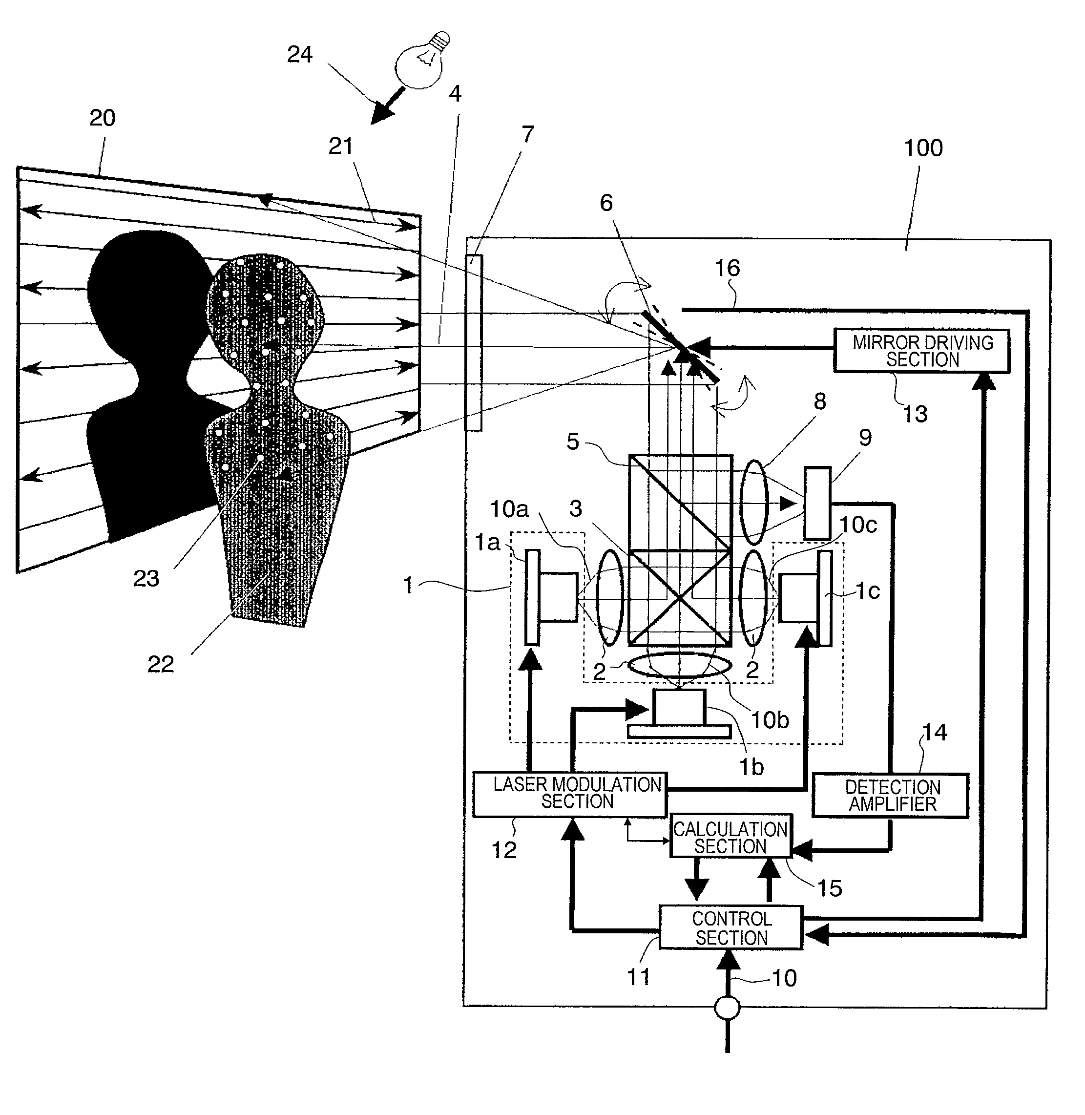
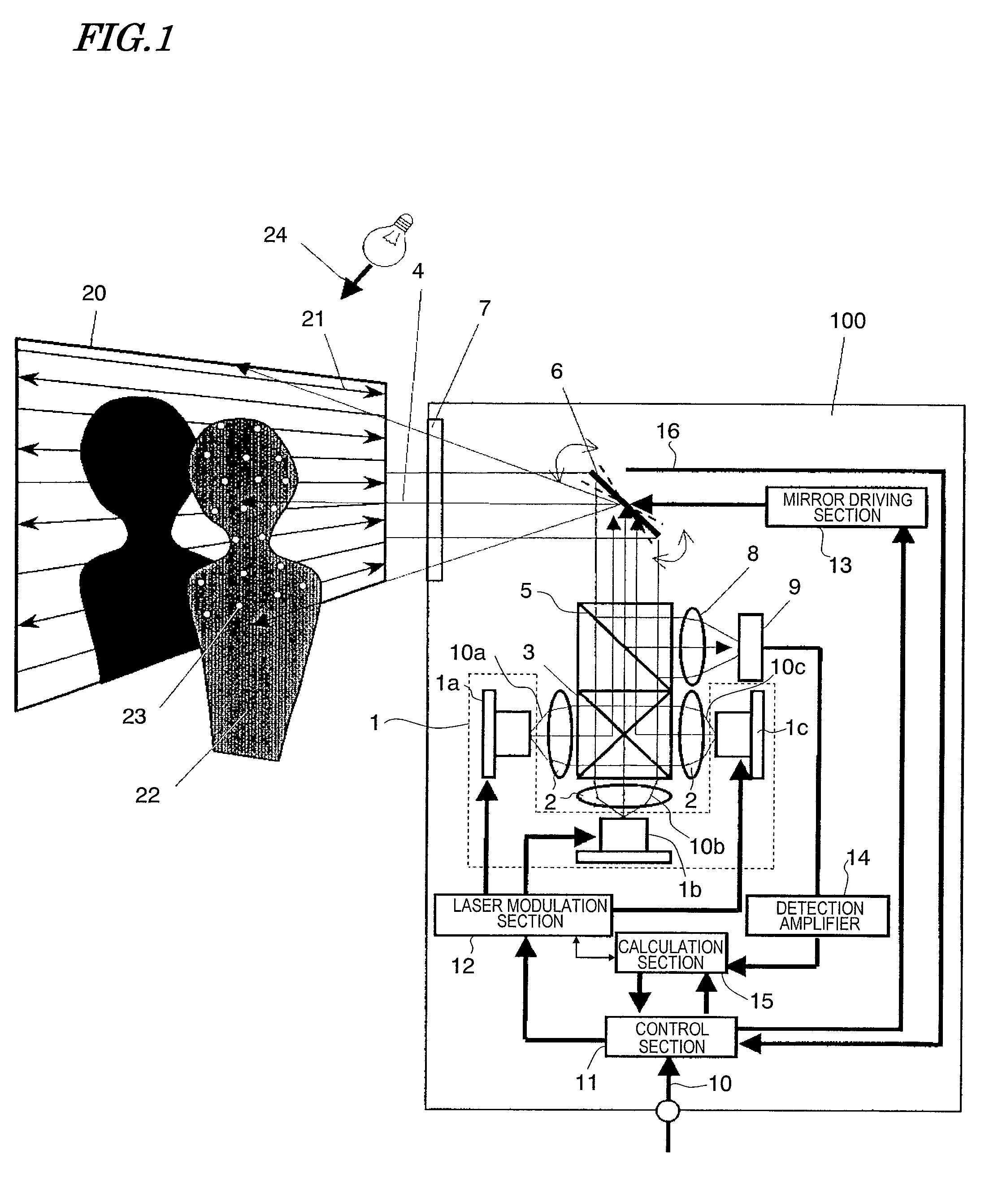
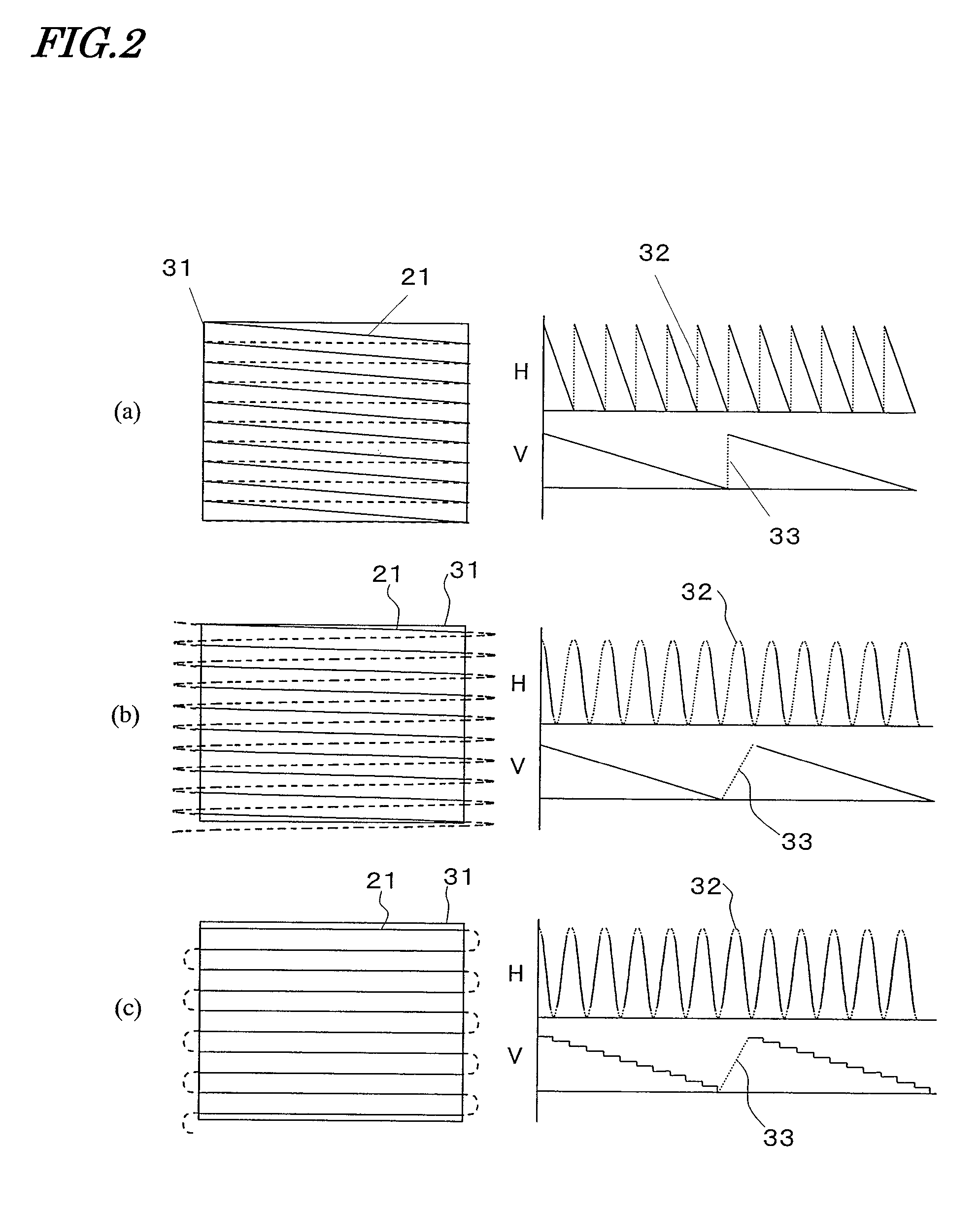
[0068]With reference to FIG. 1 to FIG. 6, a first embodiment of an image projection apparatus according to the present invention will be described. First, FIG. 1 will be referred to. FIG. 1 is a diagram showing an image projection apparatus 100 according to the present embodiment. The video projection apparatus 100 displays an image on a screen or the like with at least a portion of projected laser light. In the video projection apparatus 100, laser light and a mirror section for image displaying purposes are also utilized for an operation of detecting an image displayable region. As a result, cost reduction is realized based on a reduced number of parts, and downsizing of the video projection apparatus 100 can also be realized.
[0069]The image projection apparatus 100 includes a light source 1 for outputting laser light 10a to 10c, collimating lenses 2, a dichroic prism 3, a half mirror 5, and a mirror section 6 for allowing the laser light 10a to 10c to be reflected a...
embodiment 2
(Embodiment 2)
[0170]Next, with reference to FIG. 7 to FIG. 12, a second embodiment of an image projection apparatus according to the present invention will be described. FIG. 7 is a diagram showing an image projection apparatus 200 according to the present embodiment.
[0171]The image projection apparatus 200 measures the distance between a screen 20 and the image projection apparatus 200, and detects an obstacle (e.g., a human) from the measurement value. For example, the distance and tilt between the screen 20 and the image projection apparatus 200 are previously measured, and the measurement results are stored. Concurrently with the image displaying, distance measurement is continued, and by making a comparison between the stored distance and the newly measured distance, intrusion of an obstacle can be detected. Note that the distance between a projection target such as the screen 20 and the image projection apparatus 200 refers to the distance between the projection target and an ...
embodiment 3
(Embodiment 3)
[0199]FIG. 13 is a diagram showing an image projection apparatus 300 according to Embodiment 3 of the present invention. FIG. 14 is a perspective view describing subregions (plane determination regions); FIG. 15A is a perspective view describing an exemplary plane determination calculation for subregions; and FIG. 15B is a perspective view describing another exemplary plane determination calculation for subregions.
[0200]In the image projection apparatus 300, before performing image displaying, a distance and a tilt between the image projection apparatus 300 and an image-projected region are automatically calculated, and a substantially planar region and its planar position are extracted. At the time of image displaying, an obstacle is detected by determining whether or not the measured distance coincides with the distance to the extracted plane. Moreover, the system controller 11 divides a plane corresponding to the projection target, as obtained based on distance, int...
PUM
 Abstract
Description
Claims
Application Information
 - R&D
- Intellectual Property
- Life Sciences
- Materials
- Tech Scout
- Unparalleled Data Quality
- Higher Quality Content
- 60% Fewer Hallucinations
Browse by: Latest US Patents, China's latest patents, Technical Efficacy Thesaurus, Application Domain, Technology Topic, Popular Technical Reports.
© 2025 PatSnap. All rights reserved.Legal|Privacy policy|Modern Slavery Act Transparency Statement|Sitemap|About US| Contact US: help@patsnap.com


