
Armrest

a technology for armrests and seats, applied in the field of armrests, to achieve the effects of preventing deformation and damage of the lock mechanism, smooth reduction or expansion, and good usability

Inactive Publication Date: 2012-05-15
NHK SPRING CO LTD
View PDF11 Cites 9 Cited by
  • Summary
  • Abstract
  • Description
  • Claims
  • Application Information

AI Technical Summary

Benefits of technology

The present invention provides an armrest with a single-shaft structure that reduces bending of the lock spring during unlocking and prevents deformation and breakage. The armrest includes a stationary shaft, an armrest body, and a lock spring with a stationary-side hook and a free-side hook. The diameter of the lock spring is reduced or enlarged according to the rotation of the armrest body, so as to lock or unlock, respectively. The armrest also includes a canceling block and a cam member for unlocking and relocking the armrest body. The invention solves the problem of unstable operation and unlocking difficulty of the armrest in the prior art.

Problems solved by technology

However, the one-shaft structure armrest disclosed in Patent Document 2, has problems such that,

Method used


Image

  • Armrest
  • Armrest
  • Armrest

Examples


Embodiment Construction

[0063]The present invention will now be explained more specifically, referring to the illustrations of the embodiments. In each embodiment, corresponding members have the same numbers.

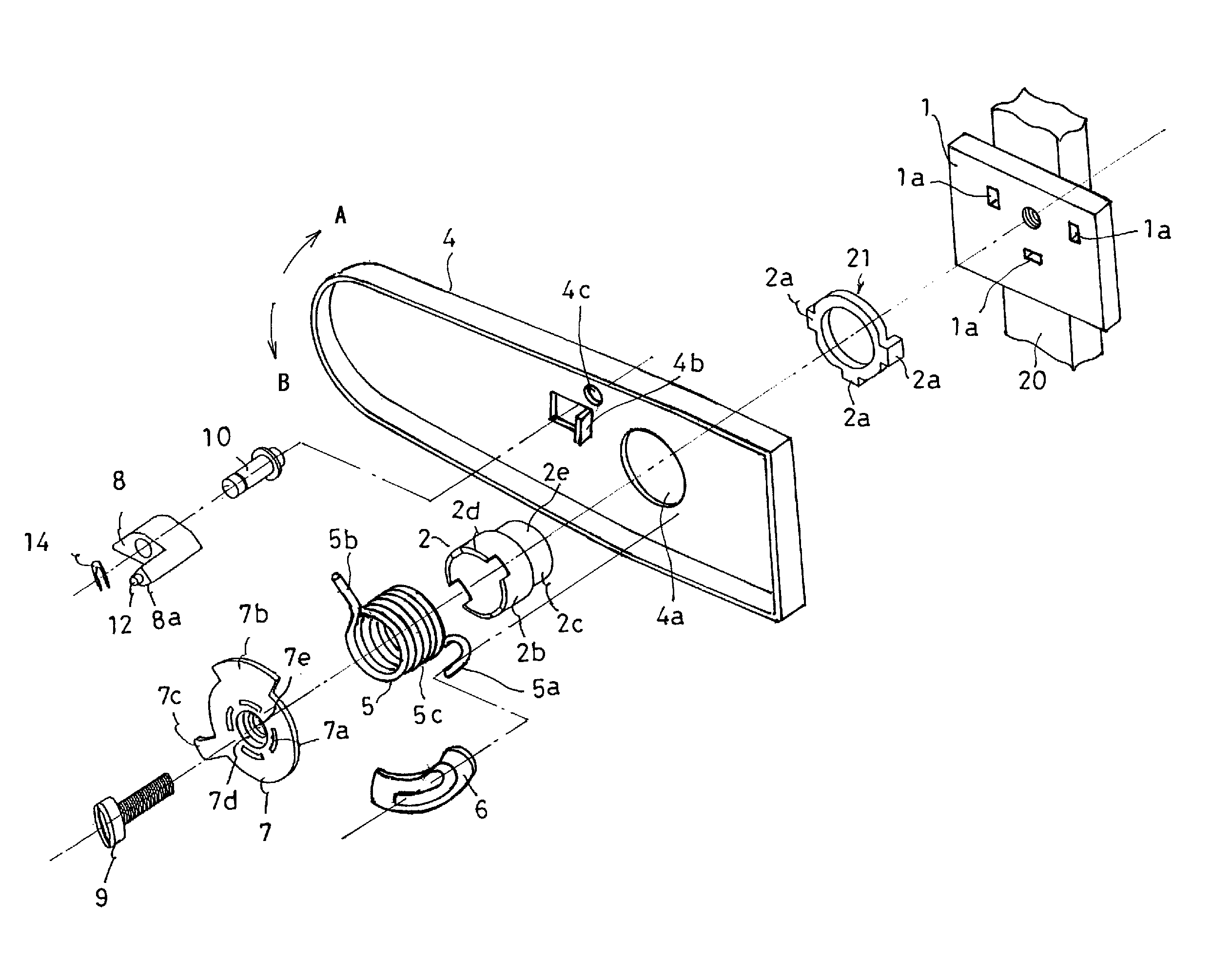
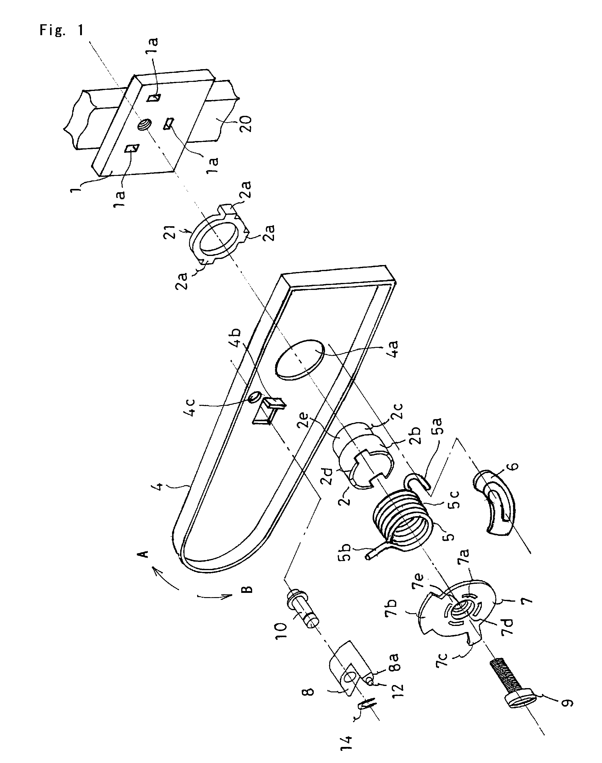
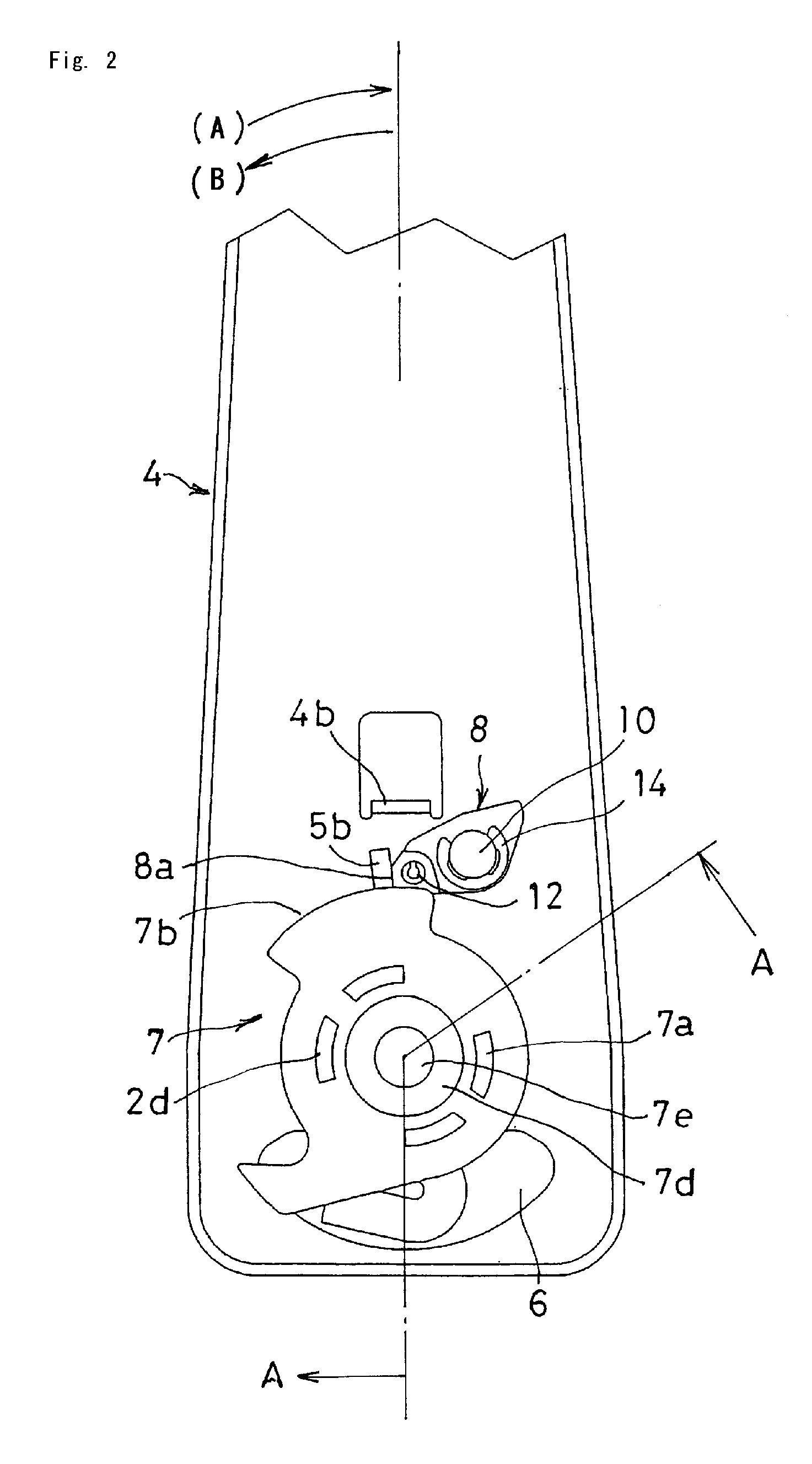
[0064]FIGS. 1 to 10 show one embodiment of the present invention. FIG. 1 is an exploded perspective view of an armrest. FIG. 2 is a front view under an assembled condition when the armrest is in the armrest-storage position. FIG. 3 is a cross-sectional view taken along the line A-A of FIG. 2. FIG. 4 shows a cross-sectional view and a front view of a lock spring. FIG. 5 is a front view of the portion of the armrest where a hook-fixing member is arranged. FIG. 6 is a plane view of the hook-fixing member. FIG. 7 is a cross-sectional view taken along the line B-B of FIG. 6. FIG. 8 is a bottom view of the hook-fixing member. FIG. 9 consists of side views of a seat and armrest, showing the entire range of sequential angle-adjustments of the armrest. FIG. 10 consists of cross-sectional views showing the actio...


PUM


Abstract

An armrest, has a stationary shaft rotatably supporting an armrest body against a seat frame. The stationary shaft is inserted, so as to have fastening tolerance, inside a coil lock spring and to have a stationary-side hook and a free-side hook. A diameter of the coil lock spring is reduced or enlarged according to a normal or a reverse rotation, respectively, of the armrest body, so as to prevent or permit, respectively, the rotation of the armrest body. One of the inside diameter of the lock spring and the outside diameter of the stationary shaft is tapered in said shaft's axial direction.

Description

CROSS-REFERENCE TO RELATED APPLICATIONS[0001]The present Application is based on International Application No. PCT / JP2007 / 063760, filed on Jul. 10, 2007, which in turn corresponds to Japanese Application No. 2006-193240 filed on Jul. 13, 2006, and priority is hereby claimed under 35 USC § 119 based on these applications. Each of these applications are hereby incorporated by reference in their entirety into the present application.TECHNICAL FIELD[0002]The present invention relates to an armrest that is mounted to a seat of a vehicle, and in particular, to a movable armrest whose angle can be adjusted in a non-step manner.BACKGROUND ART[0003]Patent Documents 1 and 2 disclose conventional, movable armrests. Each of these armrests has a structure such that the armrest body can rotate against a seat frame, and such that a coil spring is used as a lock spring for locking or unlocking the rotation of the armrest body.[0004]The armrest disclosed in Patent Document 1 has a two-shaft structur...

Claims


Application Information

Patent Timeline
Patent Type & Authority Patents(United States)
IPC IPC(8): A47C7/54B60N2/46B60N2/75
CPCA47C7/543B60N2/4613B60N2/4633B60N2/757B60N2/767
Inventor SAITO, MAKOTOMORIMOTO, TAKASHIKITAMURA
Owner NHK SPRING CO LTD
Learn More