
Gastight piston ring arrangement

a piston ring and gastight technology, which is applied in the direction of brake systems, machines/engines, transportation and packaging, etc., can solve the problems of increasing the wear rate of ptfe-based materials, which are typically used in the piston ring, and the wear rate of ptfe-based materials, which is generally not acceptable, so as to reduce the strength/extrusion resistance of the piston ring segment, reduce the surface pressure, and simplify the manufacture and assembly of the piston

Active Publication Date: 2012-05-15
HOERBIGER KOMPRESSORTECHNIK HLDG GMBH
View PDF15 Cites 20 Cited by
  • Summary
  • Abstract
  • Description
  • Claims
  • Application Information

AI Technical Summary

Benefits of technology

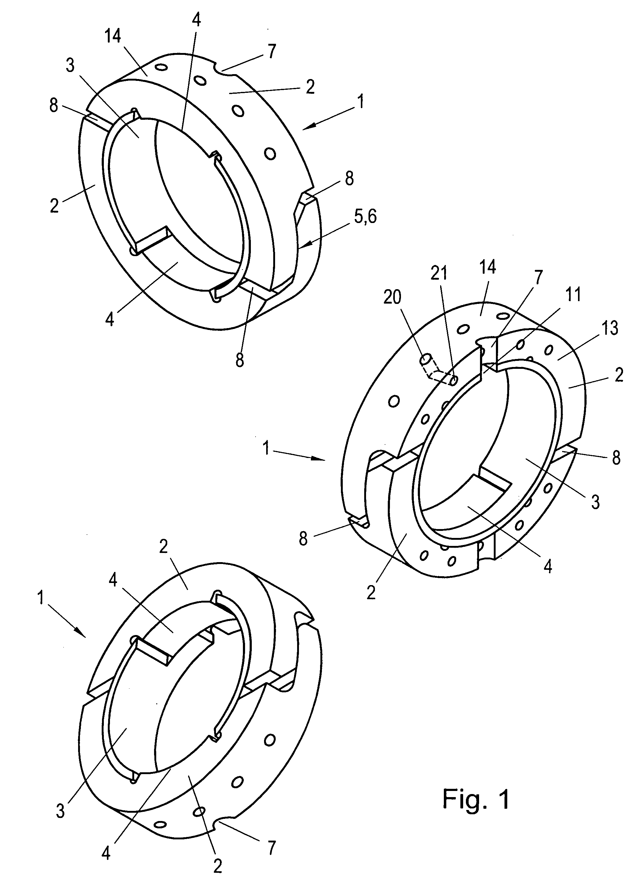
[0012]If a radial step is provided on each piston ring segment and a corresponding number of associated axial recesses are provided on the sealing ring, identical piston ring segments can be used, which substantially simplifies the manufacture and assembly of the piston ring arrangement.
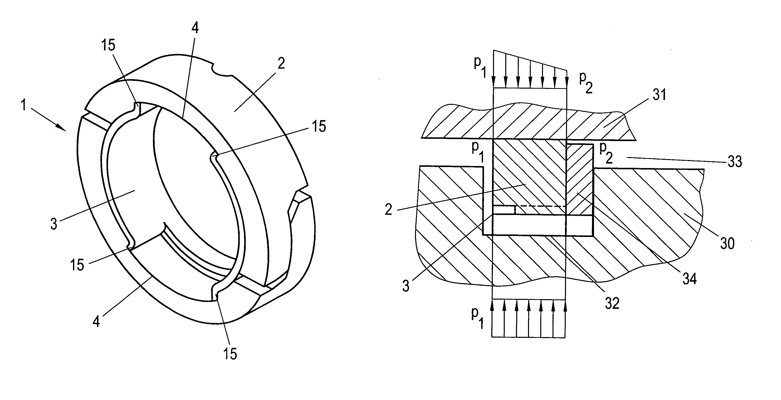
[0014]By providing in a piston ring segment a plurality of recesses which connect an end side of the piston ring segment to the outer peripheral surface of the piston ring segment, it is possible to achieve a pressure balancing which reduces the surface pressure between the piston ring and the fixed structural part. Given a careful design of the number of recesses in a piston ring segment, the degree of pressure balancing has been shown to be virtually no lower than that which is obtainable with a peripheral groove. As a result of the arrangement of recesses instead of a circumferential groove, the strength / extrusion resistance of the piston ring segment is not however reduced.
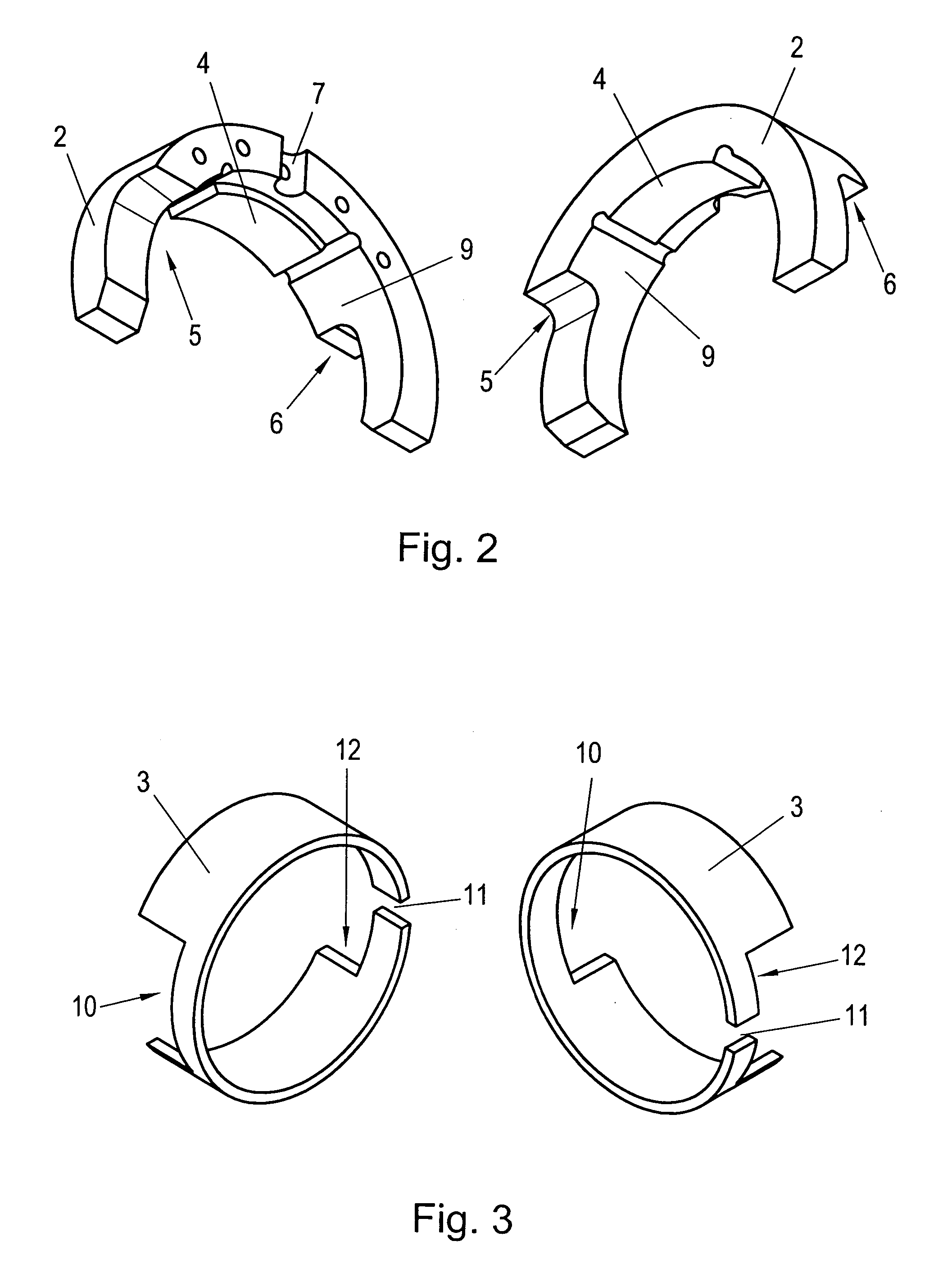
[0016]Particularly advantageously, a backup ring is provided, which bears against an end side of the piston ring segments. The use of such a backup ring can prevent the piston ring, as a result of the thermal load and the acting pressure, from being extruded into the gap between the fixed and the movable structural part and thus from being damaged or even destroyed, which would also lessen the sealing function of the piston ring arrangement. The backup ring can here be realized as a through ring or as a single-cut or multi-cut ring, in the case of a cut backup ring the backup ring segments being held together in the peripheral direction by a lock. Preferably, the backup ring segments are sealed by the lock simultaneously in the radial direction, which increases the sealing effect.

Problems solved by technology

Especially in dry-running applications, the ring wear rate, as a result of excessive surface pressures, can take on unacceptable proportions.
The wear rate of PTFE-based materials, which are typically used in piston rings, generally grows considerably as the temperature of the opposite-working surface (in this case the liner) increases.
The friction heat generated in the piston ring / liner sealing gap results in heating-up of the liner and, therefore, plays a considerable part.
More specifically, if the rings are exposed to elevated temperatures, extrusion of the piston rings into the annular gap which is formed between the piston and the cylinder and which, in order to prevent the piston from rubbing against the liner, must have a certain minimum radial measure, can additionally markedly reduce the sealing effect of the piston rings or even destroy the piston rings.
Since this joint grows bigger with increasing wear, the sealing effect of the rings also decreases markedly over time.
Especially in piston rings with small diameters and thus high bending rigidity, as are used, in particular, in high pressure applications, only composite pistons can therefore be used, which is more laborious in terms of production and maintenance.
Such piston ring constructions are known, for example, from DE 28 29 352 A1 or from U.S. Pat. No. 3,632,121 A. Particularly in high pressure applications, where such ring constructions, due to greater seal-tightness requirements, are increasingly used, it often occurs, however, that a ring, due to the thermal and mechanical load, is forced into the joint of the other ring, which can lead to deformations and a deterioration in the sealing effect.
In addition, fractures can occur as a consequence of the material weakening resulting from fully (i.e. in the radial and axial directions) covered joints.
Due to the necessary sealing in the radial and axial directions, a complex shape of the ring segments is obtained, however, which is complicated and difficult to produce.
Such a piston ring is therefore laborious in terms of its production.
The effect of this, however, is that the sealing ring, especially in high pressure applications, can deform into the joint gaps of the piston ring, which would in turn harm the sealing effect.

Method used


Image

  • Gastight piston ring arrangement
  • Gastight piston ring arrangement
  • Gastight piston ring arrangement

Examples


Embodiment Construction

[0028]A preferred embodiment of a gastight piston ring arrangement 1 according to the invention is described below with reference to FIGS. 1 to 3. In the embodiment shown, the piston ring consists of two identical piston ring segments 2. At the ends of the piston ring segments 2, viewed in the peripheral direction, an axial step 5, 6 is respectively provided in a known manner, which axial steps sealingly cooperate with associated steps of the adjacent piston ring segments 2 to obtain a seal in the axial direction. The adjacent piston ring segments 2 here lie axially one against the other and (at least from a certain level of wear) are arranged spaced apart in the peripheral direction. As a result of the radial spacing, peripheral joints 8 are formed between the piston ring segments, which radial joints are sealed by the sealing ring 3, which bears radially against the inside of the peripheral surface 9 of the piston ring segments 2. The sealing ring 3 is here a single-cut ring (join...


PUM


Abstract

A segmented piston ring assembly includes piston ring segments 2 having stepped ends 5, 6, at least one piston ring segment 2 including a radial step on a radially inner peripheral surface 9 over a part of the width of the piston ring segment 2, and a single-cut sealing ring 3, which bears radially against the inside of the peripheral surface 9 of the piston ring segments 2, the sealing ring 3 including an axial recess 10, 12 which cooperates with the radial step 4 of the piston ring segment 2 to prevent relative rotation therebetween.

Description

BACKGROUND OF THE INVENTION[0001]1. Field of the Invention[0002]The present invention relates to a gastight piston ring arrangement including a piston ring made up of a plurality of piston ring segments, the ends of which are shaped such that they are axially stepped in the peripheral direction, and the stepped ends of adjacent piston ring segments, for the formation of an axial seal, are arranged lying axially one against the other.[0003]2. The Prior Art[0004]In piston compressors, the working fluid is compressed by a piston. The sealing elements which seal the annular gap formed between the piston and the cylinder are called piston rings. In piston compressors in double-acting construction, the gas pressure in the cover-side and crank-side compression chamber respectively fluctuates between suction and discharge pressure, the two working chamber pressure patterns being mutually out of phase by a 180° crank angle. In such applications, the piston sealing system must consequently se...

Claims


Application Information

Patent Timeline
IPC IPC(8): F16J9/00F16J9/16
CPCF16J9/14F16J9/18F16J15/442F16J15/445
Inventor LINDNER-SILWESTER, TINOHOLD, CHRISTIANMOLNAR, MARTIN
Owner HOERBIGER KOMPRESSORTECHNIK HLDG GMBH
Learn More