Electrical box and stand and method for using same

a technology of electric boxes and stands, applied in the direction of machine supports, containers, domestic objects, etc., can solve the problems of increasing installation costs, difficulty in using floor boxes, and the typical floor box of only 6′′ being too short to fit within the typical concrete slab, so as to reduce the bending of electrical tubing

Active Publication Date: 2012-05-15
IPEX TECH
View PDF32 Cites 5 Cited by
  • Summary
  • Abstract
  • Description
  • Claims
  • Application Information

AI Technical Summary

Benefits of technology

[0008]Accordingly, it is an object of this invention to at least partially overcome some of the disadvantages of the prior art. Also, it is an object of at least some aspects of this invention to provide an improved electrical box stand and method which does not require the electrical boxes to be tied to any elements contained on the concrete form. Furthermore, it is an object of at least some aspects of this invention to provide an electrical stand and method which can maintain the hubs of the electrical box at different predetermined distances above the concrete form so as to decrease the bending of electrical tubing down to the hubs.
[0012]Accordingly, an advantage of one of the aspects of the present invention resides in having the electrical box secured to the stand with the hubs elevated above the concrete form a predetermined distance. This predetermined distance is preferably selected to permit the electrical tubing to be received within the electrical box with a minimum of bending. For instance, this predetermined distance is generally selected to permit the electrical tubing to avoid being routed around other obstacles in the concrete form, such as the steel rebar and / or post-tension cables. This predetermined distance is also selected to accommodate the thickness of the concrete slab and the expected flooring. Because the thickness of the slabs and the positioning of other elements in the form vary, one advantage of an aspect of this invention is to permit the same box to be maintained at any one of a plurality of different predetermined distances using the same standard box assembly thereby requiring only one type of electrical box providing a more robust system and method. This also decreases manufacturing costs because a single type of box and stand assembly need be developed and can be used with a variety of different construction environments and varied thicknesses of concrete slabs.
[0013]A further aspect of the present invention is that the stand and electrical box may be locked together at the selected distance above the concrete form. This may decrease displacement of the electrical box in the construction environment prior to the concrete being poured, such as by workmen jostling the electrical box or electrical tubing, and also while pouring of the concrete. In a preferred embodiment, the stand can be secured to the concrete form by means of screws, nails or other fastening devices and / or adhesives, now known or developed in the future, to ensure that the stand is attached to the concrete form when the electrical box has been locked in place to the stand.
[0014]An advantage of a further aspect of the present invention is that the stand has a relatively small volume, but can raise the opening of the floor box to a certain height above the concrete form to accommodate concrete slabs and flooring of differing thicknesses with a single box having a standard height, and without greatly increasing the volume of the floor box. In this aspect of the invention, the volume of the stand is preferably less than 200 cubic centimeters (cm3), more preferably less than 100 cm3 and still more preferably about 90 cm3. In this way, the smaller volume of the stand decreases the structural effect of the standard electrical box on the concrete slab, but ensures the opening of the box will be accessible from the surface once the flooring has been installed. Furthermore, this decreases the overall material and manufacturing costs of the electrical stand and box assembly.
[0015]An advantage of another aspect of the present invention relates to the stand having a small footprint such that a small surface area is in contact with the concrete form. In this way, when the concrete form is removed, little to no repair is required.

Problems solved by technology

Accordingly, one difficulty with the prior art process and system of tying electrical boxes to rebars is that additional time is required to perform this tying action, increasing the cost of installation.
However, there are several difficulties with using floor boxes.
For instance, if a typical concrete slab is 8″ thick with a further 2″ of flooring when installed, a typical floor box of only 6″ will be too short to fit within the typical concrete slab.
This is undesirable because the exposed area must be patched requiring additional labour and increasing the construction times.
This can be difficult if obstacles, such as rebar and / or post-tension cables or tendons, are located close to an electrical box requiring the electrical tubing to be routed around such obstacles.
Also, creating a bend in electrical tubing increases the difficulty to pull cable through the tubing after the concrete has been cured and could result in the electrical tubing being permanently and irrevocably damaged.

Method used


Image

  • Electrical box and stand and method for using same
  • Electrical box and stand and method for using same
  • Electrical box and stand and method for using same

Examples


Embodiment Construction

[0025]Preferred embodiments of the invention and its advantages can be understood by referring to the present drawings. In the present drawings, like numerals are used for like and corresponding parts of the accompanying drawings.

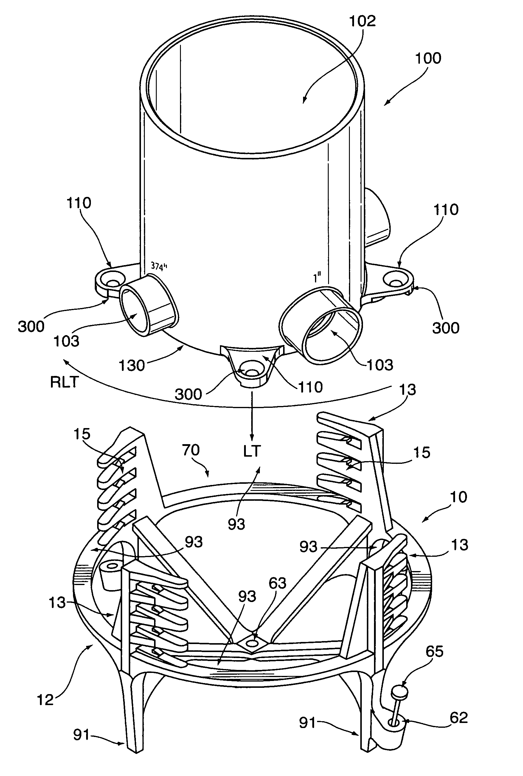
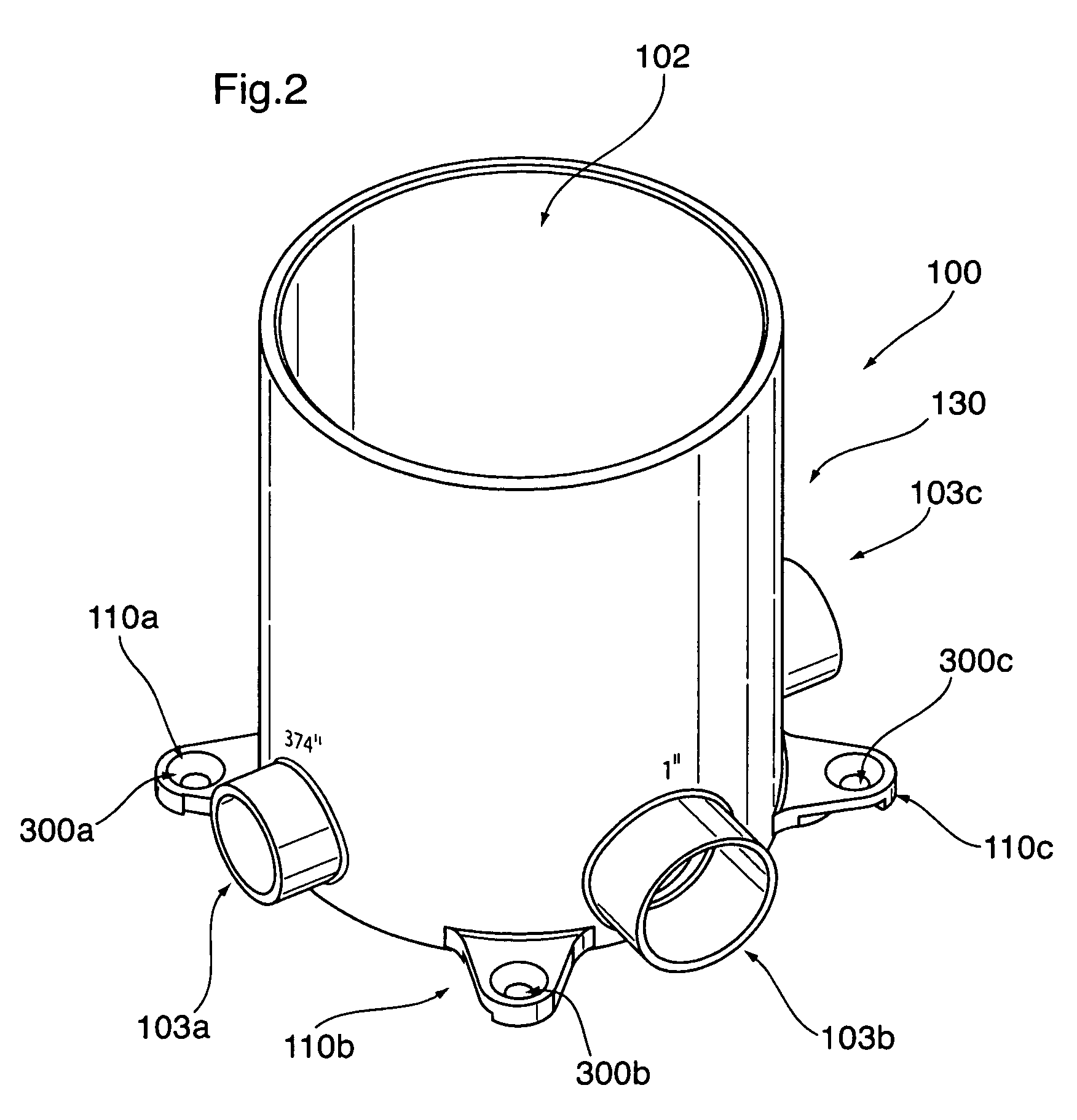
[0026]As shown in FIGS. 4, 5, 6 and 7, one embodiment of the present invention relates to an electrical box and stand assembly as shown generally by reference numeral 200. FIG. 1 illustrates the stand, as shown generally by reference numeral 10, according to one embodiment of the present invention, which combines with the electrical box, shown generally by reference numeral 100 in FIGS. 2 and 3, to form the electrical box and stand assembly 200. FIG. 5 illustrates the method of assembling the stand 10 with the electrical box 100 to form the assembly 200. FIG. 7 illustrates the assembly 200 assembled in the field with electrical tubing 8 extending from the hubs 103 of the electrical box 100 according to one embodiment of the present invention.

[0027]As illust...


PUM


Abstract

A stand for an electrical box is provided to maintain an electrical box having at least one hub a predetermined distance from a concrete form prior to and during the concrete being poured. The stand has extensions with ribs thereon at different longitudinal positions from the base permitting the electrical box to be supported by the stand at different heights with respect to the concrete form to permit access to the hubs of the electrical box with electrical tubing and to accommodate concrete slabs of different thicknesses using the same height of electrical box. The electrical box and stand assembly have a locking mechanism to lock the electrical box to the stand at the selected predetermined distance from the form. The locking mechanism has hooks which engage indentations on mounting tabs of the electrical box. The mounting tabs have grooves which guide the hooks to the indentations. The stand can be attached to the cement form during building construction to maintain the electrical box at the predetermined distance above the cement form.

Description

FIELD OF THE INVENTION[0001]This invention relates to stands for maintaining electrical boxes at various predetermined distances from the surface of a concrete form and to resist displacement prior to the concrete being poured and while the concrete is being poured.BACKGROUND OF THE INVENTION[0002]In the past, there have been many different types of electrical boxes installed in concrete or cement (concrete and cement shall be used interchangeably herein). In general, the electrical boxes together with the electrical non-metallic tubing (ENT) connected thereto are oriented in the concrete form, together with the other elements, and concrete is poured onto the form embedding them therein.[0003]In the past, electrical boxes have been supported in their final position on the form by tying to reinforcing bars (also referred to as rebars) prior to pouring the concrete form. However, instead of, or in addition to, steel rebars, post-tensioned cables or tendons have been used inside poured...

Claims


Application Information

Patent Timeline
Patent Type & Authority Patents(United States)
IPC IPC(8): H02G3/12H02G3/18
CPCH02G3/121H02G3/185
Inventor MARQUIS-MARTIN, GUILLAUME HUGO
Owner IPEX TECH
Why Eureka
Try Eureka