
Projectile-loading assembly for air-powered gun

a technology of air-powered guns and projectiles, which is applied in the field of air-powered guns, can solve the problems of air-powered guns' firing mechanism breaking down, projectile jamming, and more projectile jamming into the breech, so as to reduce the possibility of projectile jamming, increase the positional consistency of the projectile in the breech and the shooting average

Active Publication Date: 2012-05-15
WEI HO SHENG
View PDF8 Cites 7 Cited by
  • Summary
  • Abstract
  • Description
  • Claims
  • Application Information

AI Technical Summary

Benefits of technology

"The present invention provides a projectile-loading assembly for an air-powered gun that can load projectiles one by one into the same position of the breech, thereby increasing the positional consistency of the projectiles and the shooting average while preventing the jam of projectiles. The assembly includes a magazine module and a slider module that can push the projectile-loading block to open or close the projectile chamber. The projectile-loading block has an elastic piece that pushes it to slide towards the barrel when the slider module slides forwards, thereby pushing one projectile into the barrel while closing the projectile chamber. The only one projectile can be loaded into the breech in one time, which increases the positional consistency of the projectile and reduces the possibility of the jam of projectiles."

Problems solved by technology

However, conventionally, since no mechanism is provided around the breech for controlling the loading of projectiles, the projectile-pushing rod may push several projectiles in the breech in one time, which causes the jam of projectiles.
Especially, when the user tilts the muzzle of the gun downwards, more projectiles may be jammed into the breech due to their gravity.
Even, the firing mechanism of the air-powered gun may break down.

Method used


Image

  • Projectile-loading assembly for air-powered gun
  • Projectile-loading assembly for air-powered gun
  • Projectile-loading assembly for air-powered gun

Examples


Embodiment Construction

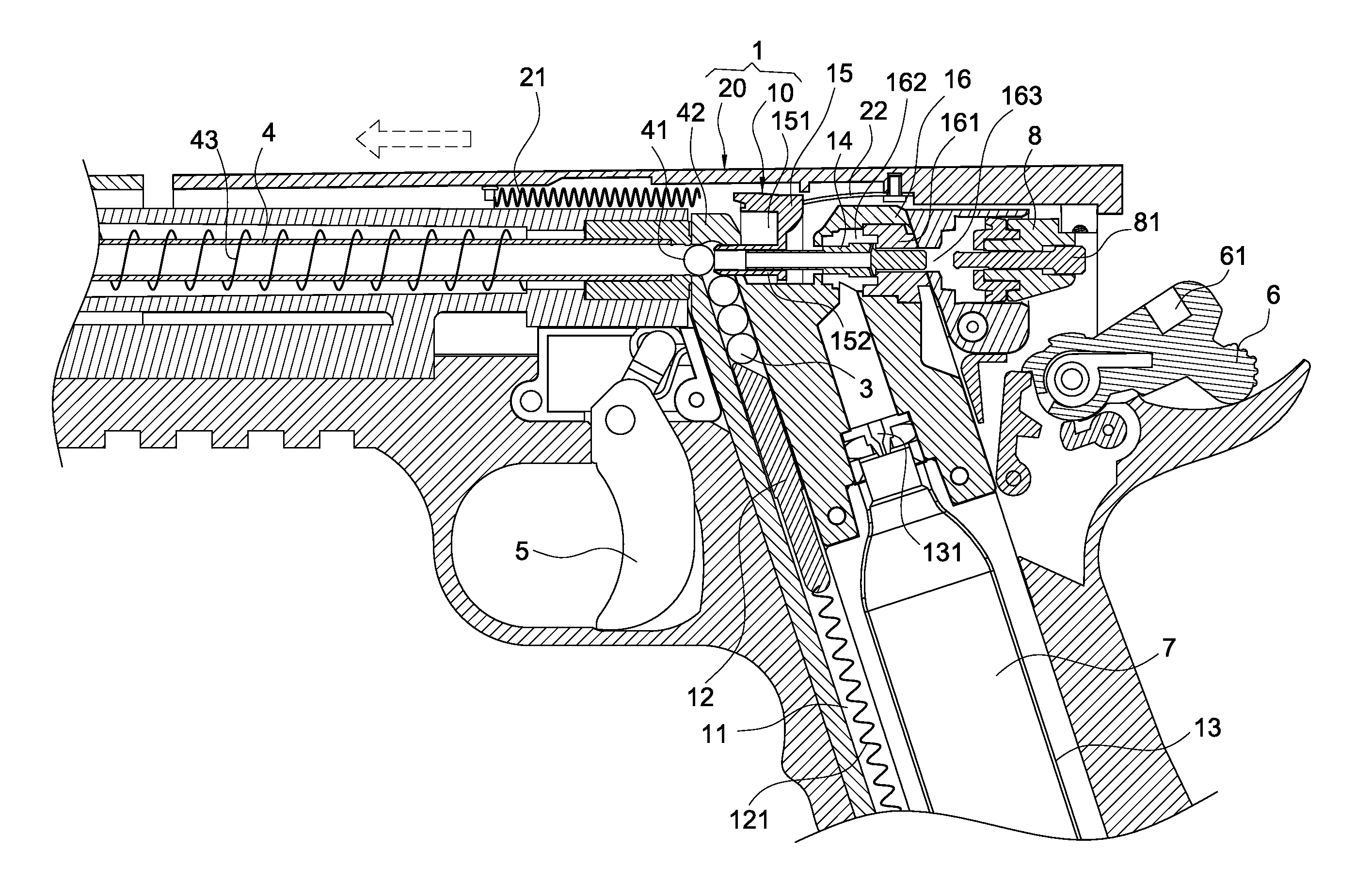
[0015]Please refer to FIGS. 1 and 2. The present invention provides a projectile-loading assembly 1 for an air-powered gun, which is configured to load a projectile 3 into a breech 41 of a barrel 4 of the air-powered gun. The projectile-loading assembly 1 includes a magazine module 10 and a slider module 20.

[0016]As shown in FIG. 2, the barrel 4 is formed into a hollow tube. The front opening of the barrel 4 is referred to as a muzzle, and the rear opening thereof is referred to as the breech 41. The upper edge of the breech 41 is formed with a protrusion 42 for blocking the projectile 3 from going beyond the upside of the barrel 4.

[0017]The magazine module 10 is inserted from the bottom of a grip of the air-powered gun into its main body. The magazine module 10 has a projectile chamber 11 for accommodating projectiles 3. The interior of the projectile chamber 11 is provided with a projectile-pushing rod 12. The projectile-pushing rod 12 is biased by a spring 121 toward the top of t...


PUM


Abstract

A projectile-loading assembly (1) for an air-powered gun is configured to load projectiles (3) in a barrel (4) and includes a magazine module (10) and a slider module (20). The magazine module (10) includes a projectile chamber (11), a rail tube (14) located over the projectile chamber (11) to be aligned with the barrel (4), and a projectile-loading block (15) sheathed the rail tube (14). The slider module (20) slides with respect to the barrel (4) and includes: a spring (21) for pushing the projectile-loading block (15) to depart from the barrel (4), and an elastic piece (22) for pushing the projectile-loading block (15) to approach the barrel (4). The elastic piece (22) pushes the projectile-loading block (15) to slide toward the barrel (4) when the slider module (20) slides forwards, thereby pushing one projectile (3) into the barrel (4) while closing the projectile chamber (11).

Description

BACKGROUND OF THE INVENTION[0001]1. Field of the Invention[0002]The present invention relates to an air-powered gun, and in particular to a projectile-loading assembly for an air-powered gun.[0003]2. Description of Prior Art[0004]Since more and more people pay attention to enjoy their leisure time, shooting projectiles (sham bullets) (such as BB balls or paintballs) has become a popular outdoor activity for modern people. Such a gun is usually powered by compressed air to thereby shoot the projectiles received in a magazine. A spring-biased projectile-pushing rod is provided in the magazine, whereby the projectiles in the magazine can be pushed into the breech of the barrel.[0005]However, conventionally, since no mechanism is provided around the breech for controlling the loading of projectiles, the projectile-pushing rod may push several projectiles in the breech in one time, which causes the jam of projectiles. Especially, when the user tilts the muzzle of the gun downwards, more ...

Claims


Application Information

Patent Timeline
Patent Type & Authority Patents(United States)
IPC IPC(8): F41B11/02
CPCF41B11/723F41B11/56
Inventor WEI, HO-SHENG
Owner WEI HO SHENG
Learn More