A semiconductor laser electrode wire fast bonding device and bonding method
An electrode wire and laser technology, applied in the direction of semiconductor lasers, lasers, laser parts, etc., can solve the problems of difficulty in ensuring the consistency of electrode bonding position, difficulty in adjusting electrode wire position, low efficiency of manual operation, etc., so as to avoid product contamination. , Simple structure and low cost
- Summary
- Abstract
- Description
- Claims
- Application Information
AI Technical Summary
Problems solved by technology
Method used
Image


Examples
Embodiment 1
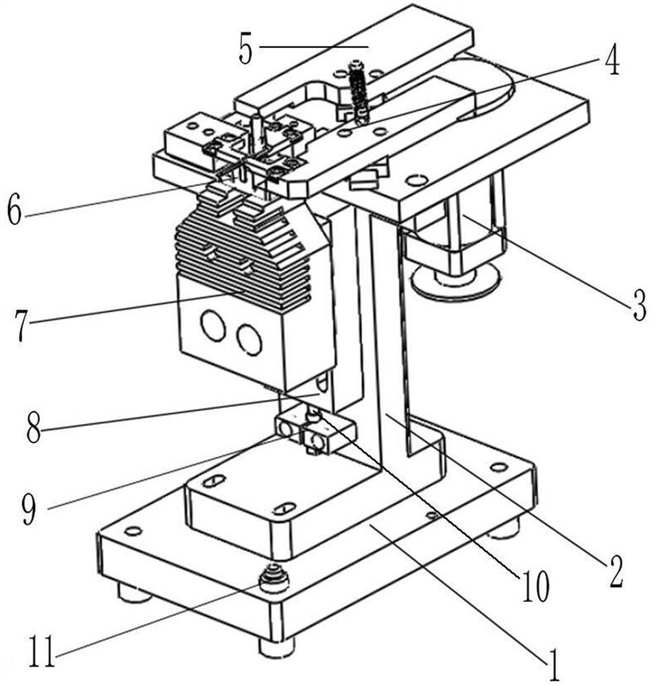
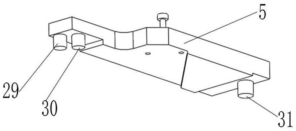
[0043] The positioning block driving mechanism I can have the following structure, which includes a motor 3 installed on the bracket 2, an elliptical cam 12 installed on the output shaft of the motor 3, a slide rail I 16 horizontally installed on the upper end of the bracket 2 along an oblique direction, and Horizontally installed on the slide rail II 18 on the upper end of the bracket 2 along the left and right direction, the lower end of the moving block I 4 is slidably installed on the lower right end of the slide rail I 16 through the slider I 13, and the lower end of the moving block II 5 is slidably installed on the slide rail I 16 through the slider II 14 The upper left end of the rail I 16, the moving block III 17 is located at the front end of the moving block II 5 and is slidably installed on the slide rail II 18, the positioning block I 25 is installed on the moving block III 17, and the positioning block II 26 is installed on the moving block I 4, one end of the ten...
Embodiment 2
[0045] The above-mentioned positioning mechanism includes the positioning groove I 35 arranged on the inner side of the positioning block I 25 or the positioning block II 26, the positioning groove II 36 arranged above the positioning groove I 35, and the positioning groove 37 arranged at the front end of the positioning groove II 36, when the positioning block When the driving mechanism I drives the positioning block I 25 and the positioning block II 26 to move inwardly, the left and right ends of the heat sink 28 located at the upper end of the positioning groove 33 are respectively tightened in the two positioning grooves I 35, and the front surface of the heat sink 28 and the The front ends of the two positioning grooves I 35 are in contact with each other, the left and right ends of the insulating sheet 38 are respectively tightened in the two positioning grooves II 36, and the left and right ends of the electrode wire 39 are respectively inserted into the corresponding pos...
Embodiment 3
[0047] The positioning block driving mechanism II can have the following structure, which includes a slide rail III 20 horizontally arranged on the bracket 2 along the front-rear direction, a moving block IV 19 slidably installed on the slide rail III 20, and a positioning block III 27 mounted on the moving block IV 19 Above, one end of connecting rod II 23 is rotatably mounted on the front end of moving block II 5 through bearing II 30, the other end is hingedly connected with moving block IV 19, one end of tension spring III 24 is connected with connecting rod II 23, and the other end is connected with fixed Rod 34 is connected. When the moving block II 5 slides upward to the left along the slide rail I 16, the moving block II 5 drives the connecting rod II 23 to swing, and the connecting rod II 23 transfers the upward movement of the moving block II 5 when it moves obliquely to pull the moving block IV 19 Slide upward along the slide rail III 20 to drive the positioning blo...
PUM
 Abstract
Description
Claims
Application Information
 - Generate Ideas
- Intellectual Property
- Life Sciences
- Materials
- Tech Scout
- Unparalleled Data Quality
- Higher Quality Content
- 60% Fewer Hallucinations
Browse by: Latest US Patents, China's latest patents, Technical Efficacy Thesaurus, Application Domain, Technology Topic, Popular Technical Reports.
© 2025 PatSnap. All rights reserved.Legal|Privacy policy|Modern Slavery Act Transparency Statement|Sitemap|About US| Contact US: help@patsnap.com