Thin-wall drill cylinder clamping device of thin-wall drill welding machine

A clamping device and thin-wall drill technology, which is applied in the field of machine tools, can solve the problems of occupying the space behind the V-shaped clamping block, affecting the installation of other devices, and the long time required for adjustment, so as to ensure the installation space of brazing heating equipment Or laser welding equipment installation space, improve production efficiency, reduce the effect of occupying space

Pending Publication Date: 2020-10-13
台州市圣西亚金刚石设备有限公司
View PDF3 Cites 0 Cited by
  • Summary
  • Abstract
  • Description
  • Claims
  • Application Information

AI Technical Summary

Problems solved by technology

[0005] Later, someone proposed an alignment adjustment structure between the cylinder body and the cutter head in the diamond thin-wall drill welding machine (application number: 201520297385.2). The cutter head clamping device holds the cutter head in the same thickness direction, and there is a locking structure between the slide plate and the frame that can make the slide plate stationary; although this structure can adjust the position of the V-shaped clamping block, it can realize the enlargement of the thin-wall drilling welding machine. 1. The structure is complex and the manufacturing cost is high; 2. A large amount of space behind the V-shaped clamping block is occupied, which affects the installation of other devices; 3. It is necessary to repeatedly adjust the V-shaped clamping block in actual production. The position of the clamping block and the position of the cylinder and the cutter head are repeatedly tested, and there is a problem that it takes a long time to adjust

Method used


Image

  • Thin-wall drill cylinder clamping device of thin-wall drill welding machine
  • Thin-wall drill cylinder clamping device of thin-wall drill welding machine
  • Thin-wall drill cylinder clamping device of thin-wall drill welding machine

Examples


Embodiment 1

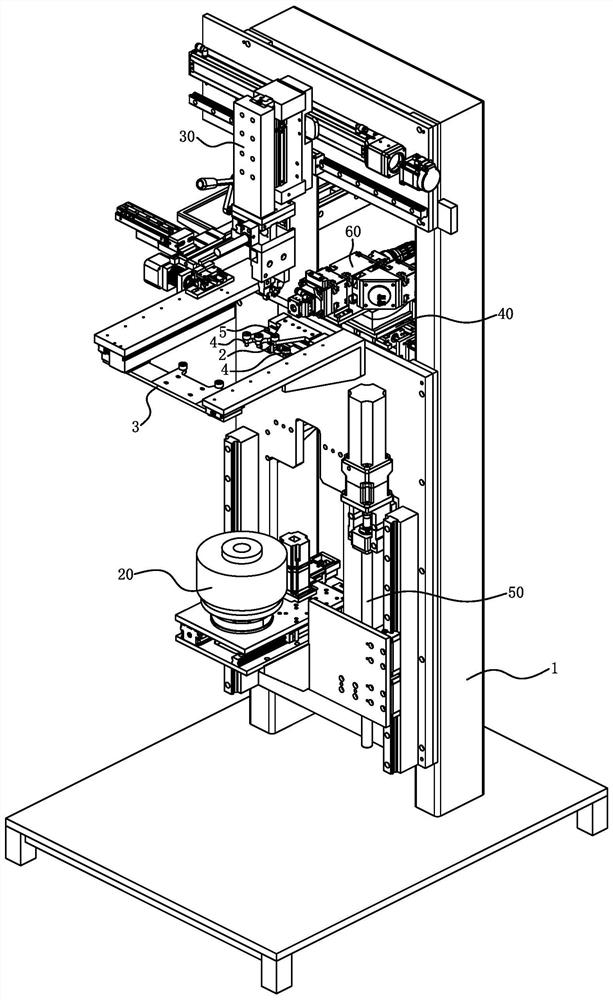
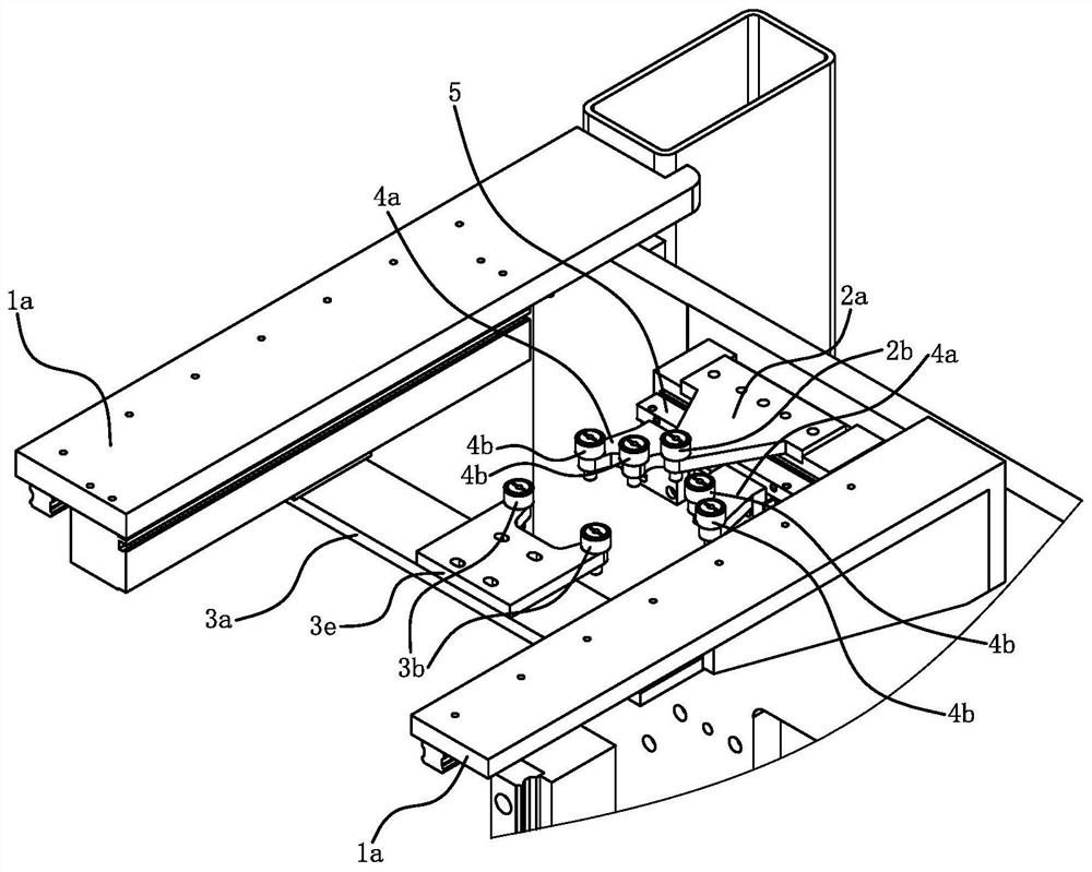
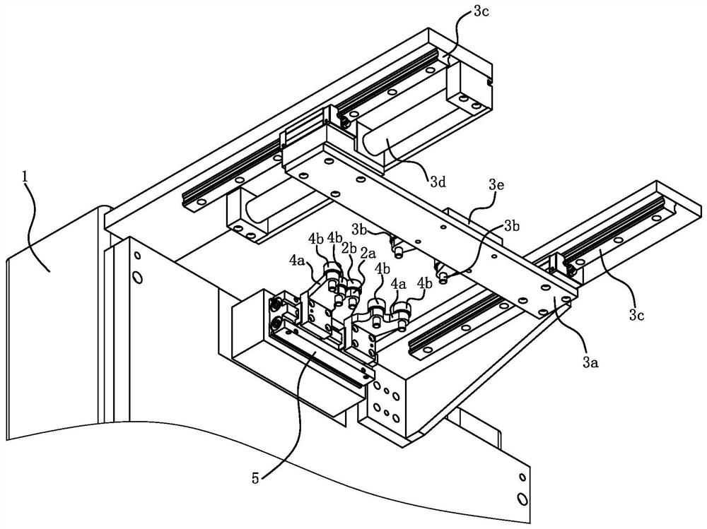
[0028] Embodiment one: if Figure 1 to Figure 3 As shown, the thin-walled drill welding machine includes a frame 1, a cylinder indexing and rotating device 20, a thin-walled drill cylinder 10 clamping device, a cutter head clamping device 30 and a laser head driving device 40; the cylinder indexing and rotating device 20 is connected with the frame 1 through the lifting mechanism 50, and the thin-walled drill cylinder clamping device and the cutter head clamping device 30 are all installed on the frame 1; the cylinder indexing and rotating device 20, the thin-wall drill cylinder clamping The device and the cutter head clamping device 30 are arranged sequentially from bottom to top. When the thin-walled drill cylinder 10 is vertically installed on the cylinder indexing and rotating device 20 , the thin-walled drill cylinder clamping device can clamp the top of the thin-walled drill cylinder 10 . The laser head driving device 40 is positioned at the rear side of the thin-walled...

Embodiment 2

[0037] Embodiment 2: The structure and principle of this embodiment are basically the same as those of Embodiment 1. The basic similarities are no longer redundantly described, and only the differences are described. The difference lies in: the rear side backer 4 and the frame 1 The connection structure and the use of different driving parts, the rear side backers 4 are connected with the frame 1 through the second guide rail, the frame 1 is rotatably connected with a synchronous gear, and the two rear side backers 4 are connected with Gear racks that mesh with each other. The number of driving parts is one group, and the driving parts are springs or cylinders; the two groups of rear side mounts 4 are connected through the driving parts. According to the actual situation, the quantity of the driving parts can also adopt two groups, so the two groups of rear side backers 4 are connected with the two groups of driving parts in one-to-one correspondence.


PUM

PropertyMeasurementUnit
diameteraaaaaaaaaa

Abstract

The invention provides a thin-wall drill cylinder clamping device of a thin-wall drill welding machine, and belongs to the technical field of machine tools. The problems that in an existing thin-walldrill welding machine, an alignment adjusting structure of a cylinder and a tool bit is complex, and the manufacturing cost is high are solved. The thin-wall drill cylinder clamping device comprises aset of rear center backer fixed to a rack, a set of front extrusion assembly is arranged on the front side of the rear center backer, and the front extrusion assembly is installed on the rack; rear side backers are arranged on the left side and the right side of the rear center backer and connected with the rack, and a driving piece capable of reducing the distance between the two rear side backers is installed on the rack; and when the thin-wall drill cylinder is clamped, the outer side face of the thin-wall drill cylinder makes line contact with the rear center backers, and the two rear side backers abut against the outer side face of the thin-wall drill cylinder. Rear side quadrant points of the thin-wall drill cylinder lean against the rear center backers, and it is guaranteed that the positions of the rear side quadrant points are the same after the thin-wall drill cylinders of different diameters are clamped.

Description

technical field [0001] The invention belongs to the technical field of machine tools, and relates to a welding machine, in particular to a thin-wall drill cylinder clamping device of a thin-wall drill welding machine. Background technique [0002] Thin-walled drills are also called water drills and hollow drills. Thin-walled drills include a cylinder and a cutter head welded on one end of the cylinder. [0003] When welding thin-walled drills, the cylinder needs to be clamped and positioned on the frame, so as to ensure the welding accuracy. For this reason, the inventor has proposed a cylinder positioning device in a thin-walled drilling and welding machine (application number: 201010173633.4), which includes a V-shaped block, a guide rod and a positioning mechanism with a positioning piece. The positioning piece is pressed on the cylinder. The barrel rests on the V-block. Due to the different diameters of the thin-walled drills, the positions of the rear quadrant points ...

Claims


Application Information

Patent Timeline
Patent Type & Authority Applications(China)
IPC IPC(8): B23K26/02B23K26/21B23K26/70
CPCB23K26/02B23K26/21B23K26/702
Inventor 项大清
Owner 台州市圣西亚金刚石设备有限公司
Why Eureka
Try Eureka