Generating and visualizing an ion beam profile

a technology of generating and visualizing ion beams, applied in the field of generating and visualizing ion beam profiles, can solve the problems of slowing down the process of treatment planning, dose calculation, and localized cell damage with minimal damage to surrounding healthy tissue, and achieves fast and reliable determination and visualization, fast and reliable, and easy implementation.

Inactive Publication Date: 2012-05-08
SIEMENS HEALTHCARE GMBH
View PDF4 Cites 0 Cited by
  • Summary
  • Abstract
  • Description
  • Claims
  • Application Information

AI Technical Summary

Benefits of technology

[0006]The present embodiments may obviate one or more of the drawbacks or limitations inherent in the related art. For example, in one embodiment, a method for generating and visualizing an ion beam profile which is fast, reliable and easy to implement and which respects the particular characteristics of an ion beam is provided. In another example, a therapy planning system and a computer software, which allows a fast and reliable determination and visualization of an ion beam profile, is provided.
[0009]Compared to methods that visualize characteristics of an ion beam by presenting a dose distribution based on a dose calculation, the method provides a fast generation and visualization of the ion beam profile. The method does not require any dose calculation in order to create and / or to visualize an ion beam profile.
[0014]The ion beam profile may be displayed with images created from the image data set with a corresponding spatial relationship. The ion beam profile may, for example, be displayed together with structures of the object that is to be irradiated, for example, together with the target region or together with the target region and the surrounding structures. This allows a user to easily verify whether the ion beam profile passes the object at the right location.
[0023]The ion beam profile that is characterized by a mesh can easily be visualized on a graphical display. The mesh like structure may be represented on a graphical display.

Problems solved by technology

The particles of the particle beam interact with the target in a relatively delimited region resulting in localized cell damage with minimal damage of the surrounding healthy tissue.
Dose calculation, however, is time-consuming and can slow down the process of treatment planning.

Method used


Image

  • Generating and visualizing an ion beam profile
  • Generating and visualizing an ion beam profile
  • Generating and visualizing an ion beam profile

Examples


Embodiment Construction

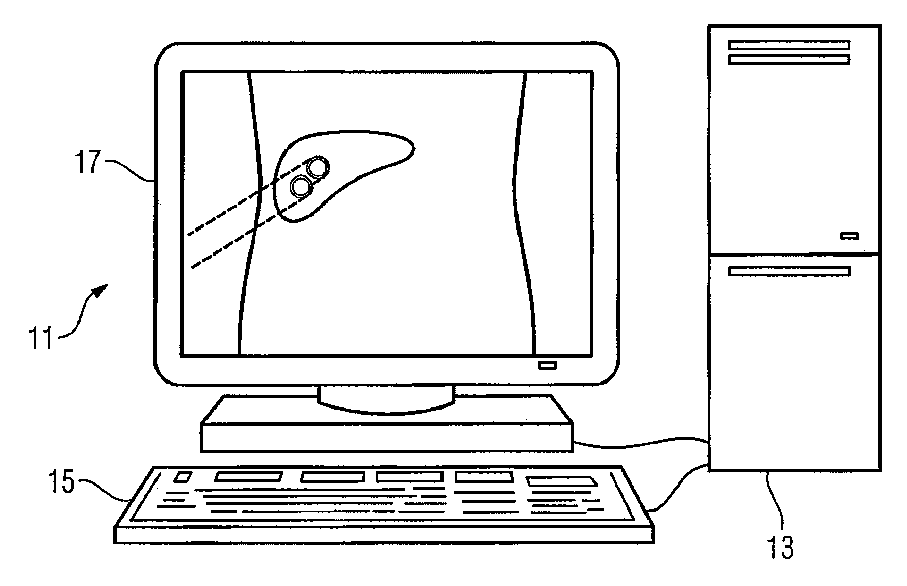
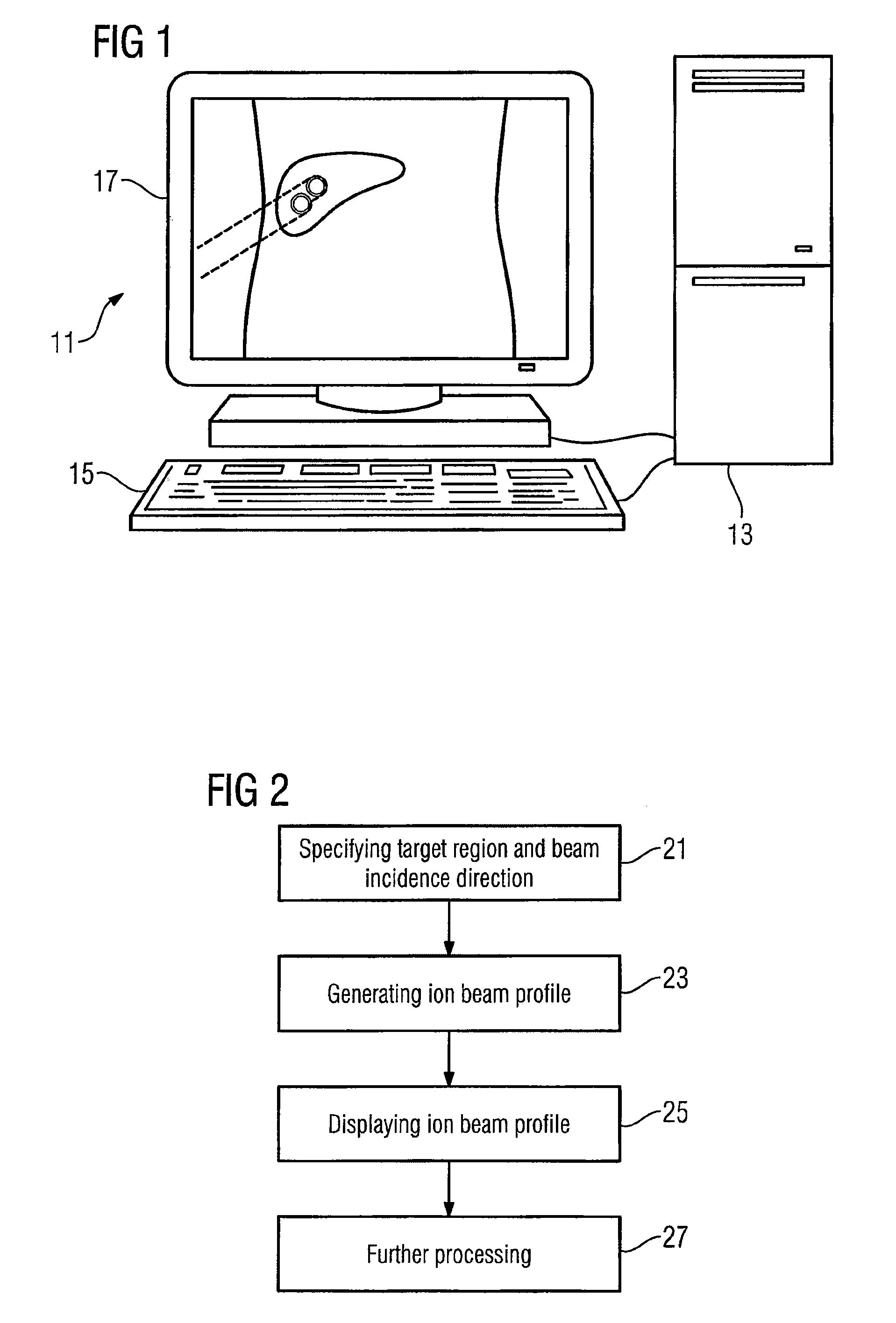
[0031]FIG. 1 shows a treatment planning system 11. The treatment planning system 11 includes a computing device 13 for performing calculations during treatment planning. The treatment planning system 11 includes at least one input device 15 that allows a user to interact with the treatment planning system 11 and at least one output device 17 for presenting information. A treatment planning system 11 may be a computer, on which appropriate treatment planning software runs.

[0032]FIG. 2 shows a schematic diagram of a method for generating and visualizing an ion beam profile. In act 21, a target region and an incidence direction of the particle beam are specified. The target region and / or the incidence direction of the particle beam may be specified, for example, by using images created from an image data set of an object which is to be irradiated. A user can, for example, delineate sketches of the target region on an image of the image data set by using the input device.

[0033]In act 23...


PUM


Abstract

A method for generating and visualizing an ion beam profile is provided. The method includes specifying an incidence direction of a particle beam, specifying a target region that is to be irradiated by said particle beam, creating an ion beam profile from points that are located on a downstream side of the target region or that are located in front of the target region and project onto the contour of the target region with respect to the incidence direction, and displaying a graphical representation of the ion beam profile.

Description

[0001]This patent document claims the benefit of European Patent Application No. EP 08002307 filed on Feb. 7, 2008, which is hereby incorporated by reference.BACKGROUND[0002]The present embodiments relate to generating and visualizing an ion beam profile. The ion beam profile may be used during treatment planning for a particle therapy treatment.[0003]Particle therapy is commonly used in the field of oncology to treat localized forms of cancer and other afflictions. For particle therapy, particles such as protons, carbon ions or other particles are accelerated to high energies. The particles form a beam that is directed to a target volume. The particles of the particle beam interact with the target in a relatively delimited region resulting in localized cell damage with minimal damage of the surrounding healthy tissue. Particle therapy can be used in fields where no treatment of a patient occurs, for example, in research and development activities which involve irradiation of materi...

Claims


Application Information

Patent Timeline
Patent Type & Authority Patents(United States)
IPC IPC(8): A61N5/00A61N5/10
CPCA61N5/103A61N2005/1087
Inventor MURALI, SHETTIHALLI
Owner SIEMENS HEALTHCARE GMBH
Why Eureka
Try Eureka