Image rotation adaptor

a technology of rotating adapters and adapters, which is applied in the field of rotating adapters, can solve the problems of increasing the size of the apparatus, not being able to configure an existing camera, and not being able to configure an existing lens, and achieve the effect of easy rotation operation

Inactive Publication Date: 2012-05-01
FUJIFILM CORP +1
View PDF25 Cites 0 Cited by
  • Summary
  • Abstract
  • Description
  • Claims
  • Application Information

AI Technical Summary

Benefits of technology

[0013]The present invention has been made in view of the above described circumstances. An object of the present invention is to provide an image rotation adaptor which can be used with an existing camera and an existing image capturing lens and which is capable of giving a special effect to a video image captured by the camera.
[0019]Further, in the present invention, the first prism is provided at a position before the image is once formed in the adapter, and is formed to have the optical path length close to the optical path length of the prism (for example, color separation prism or the like) incorporated in the camera main body. Thus, it is possible to form the object image on the light receiving surface of the image pickup device without deteriorating the performance of the image capturing lens. That is, in the image capturing lens, the aberration, and the like, is designed in consideration of the prism incorporated in the camera main body. Thus, when the first prism is formed to have the optical path length close to the optical path length of the prism incorporated in the camera main body, it is possible to form the image in the adaptor in the state in which the aberration, and the like, is taken into account. Further, when the image formed in the adaptor is re-formed by the relay optical system, it is possible to form the image on the light receiving surface of the image pickup device without deteriorating the performance of the image capturing lens.
[0020]In this way, according to the image rotation adapter of the present invention, it is possible to perform the special image capturing in which the image is rotated, by using an existing camera and an existing image capturing lens without deteriorating the performance of the lens. Further, the configuration can also be made compact.
[0022]According to the second aspect of the present invention, the first prism and the second prism are respectively configured so as to reflect the incident object light at least three times or more and to emit the reflected object light. This makes it possible to reduce the whole length of the adaptor and thereby to make the configuration of the adaptor compact.
[0024]According to the third aspect of the present invention, the second prism is rotatably driven according to the instruction of rotation from the input device. Thereby, the rotation operation can be easily performed.
[0025]According to the present invention, by using an existing camera and an existing image capturing lens, it is possible to give a special effect to a video image captured by the camera.

Problems solved by technology

However, the method of giving a special effect to a video image by using a special filter, as described in patent documents 1 to 4, has a disadvantage that the filter is exchanged by using a turret mechanism, so that the size of the apparatus is increased.
Further, the method of giving a special effect by rotating a video image by rotating an image pickup device has a disadvantage that a mechanism for rotating the image pickup device needs to be provided on the camera side and that such configuration is not possible in an existing camera.
Further, it is also possible to provide the mechanism for rotating the image pickup device on the lens side, but even in such case, there is a disadvantage that such configuration is not possible in an existing lens.
Further, when the mechanism for rotating the image pickup device is provided on the camera side, there is a disadvantage that the size of the camera is increased and that the configuration of the camera becomes complicated.
Further, when the image pickup device is rotated, there is also a disadvantage that a noise is generated in a signal outputted from the image pickup device.

Method used


Image

  • Image rotation adaptor
  • Image rotation adaptor
  • Image rotation adaptor

Examples


Embodiment Construction

[0032]In the following, preferred embodiments of an image rotation adaptor according to the present invention will be described in detail with reference to the accompanying drawings.

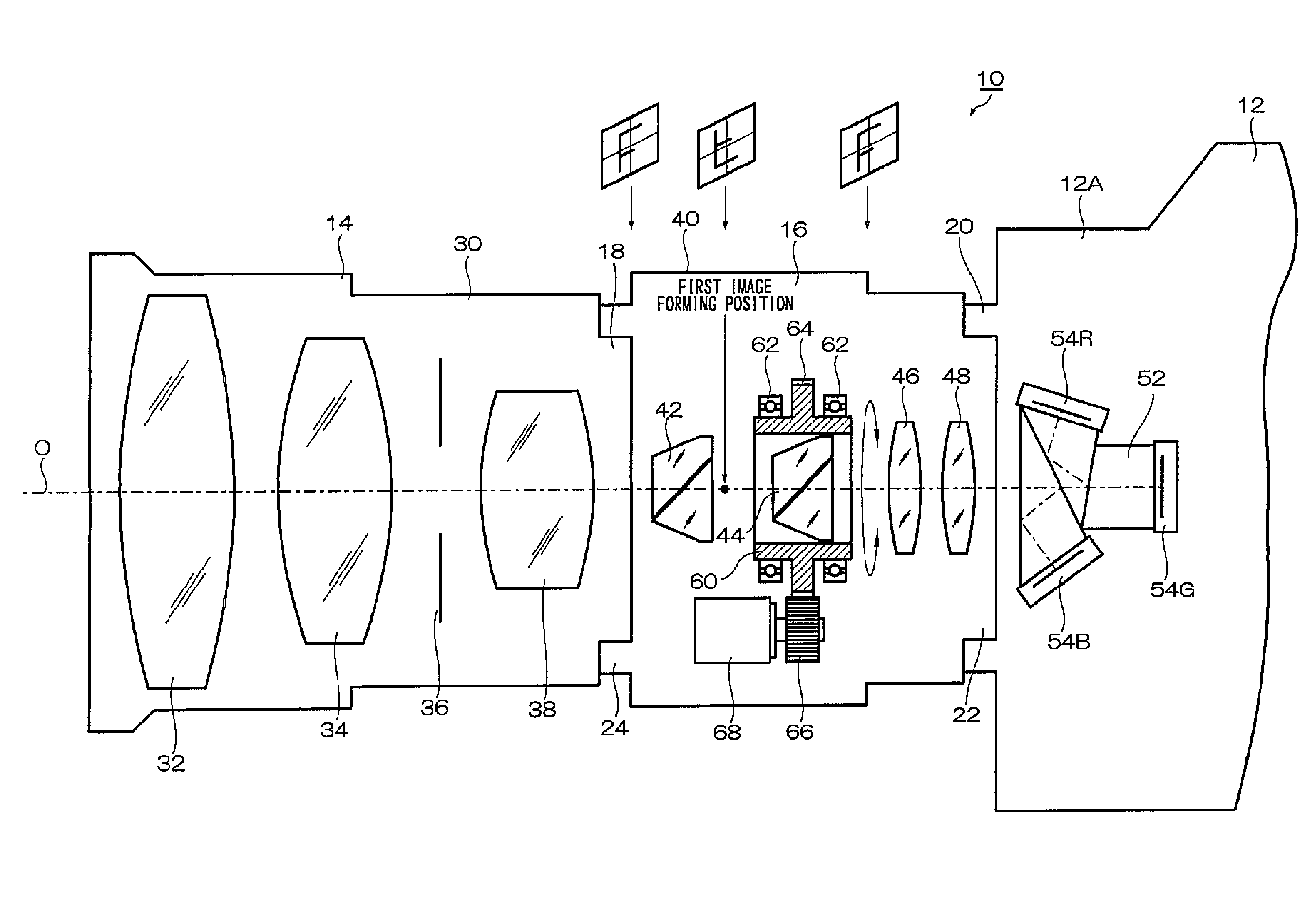
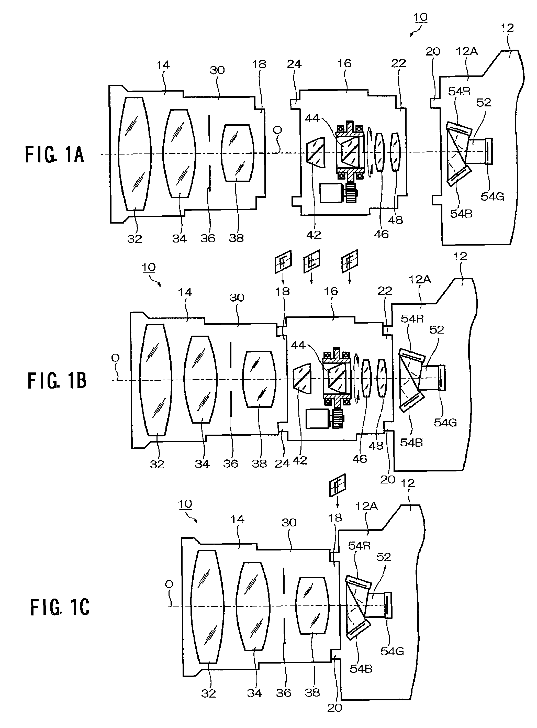
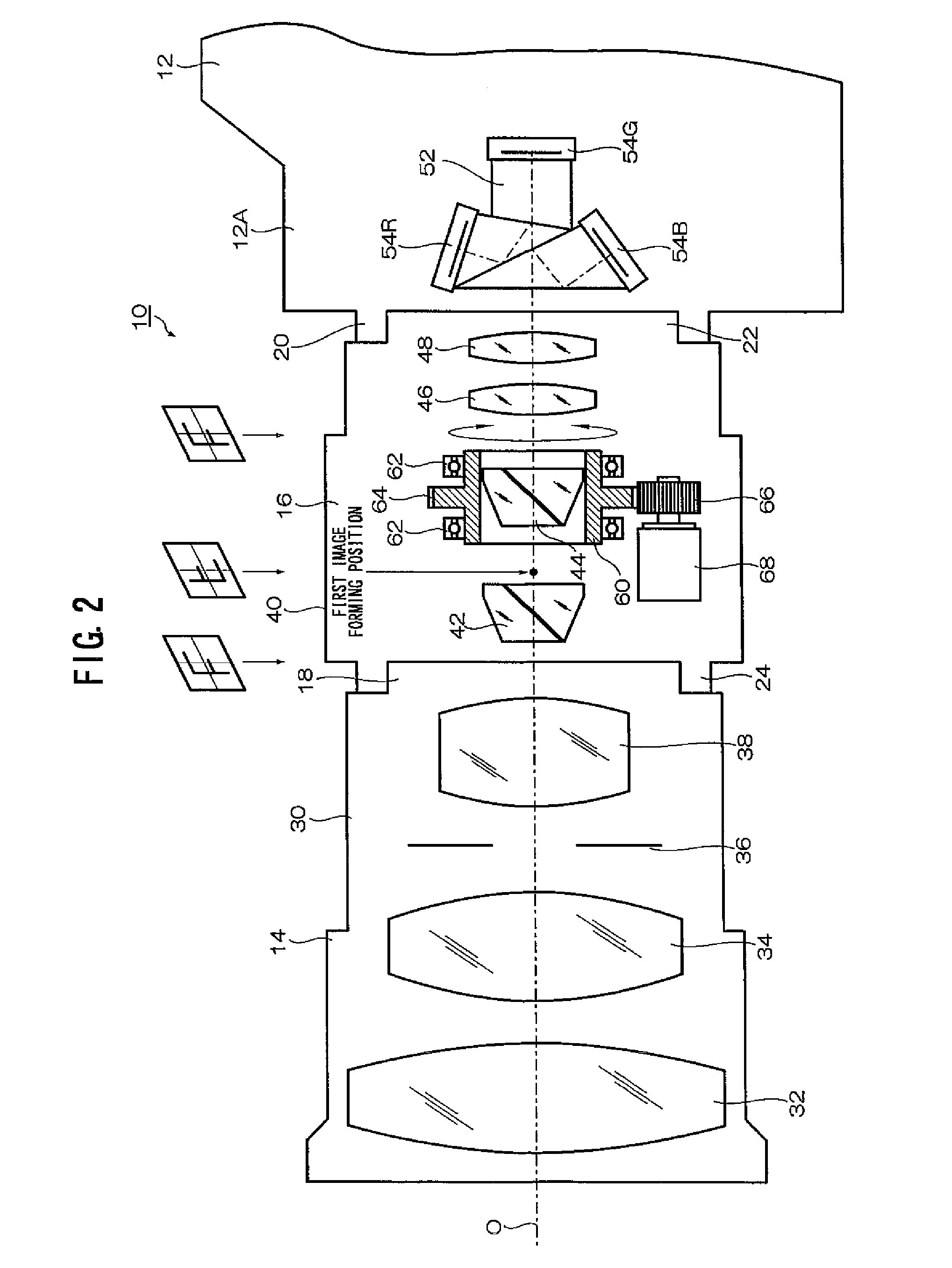
[0033]FIGS. 1A to 1C show a system configuration of a television camera system in which an image rotation adaptor according to the present invention is incorporated.

[0034]As shown in FIG. 1A, the television camera system 10 is configured by a television camera 12, an image capturing lens 14, and an image rotation adaptor 16.

[0035]The image rotation adaptor 16 is an adapter used to give a special effect to a video image captured by the television camera 12 by rotating the video image, and is mounted between the television camera 12 and the image capturing lens 14 as required. That is, as shown in FIG. 1B, when the special effect is given to the video image by rotating the video image, the image rotation adaptor 16 is mounted between the television camera 12 and the image capturing lens 14. When the specia...


PUM


Abstract

An image rotation adapter that is configured to be detachably mounted between an image capturing lens and a camera main body in a camera and includesa first prism configured to invert the object image passed through the image capturing lens by reflecting an odd number of times object light passed through the image capturing lens anda second prism that is supported rotatably about the optical axis, and that is configured to further invert the object image inverted by the first prism by reflecting an odd number of times the object light passed through the first prism;an operation device configured to perform an operation to rotate the second prism; anda relay optical system configured to re-form the object image passed through the second prism on the light receiving surface of the image pickup device.

Description

BACKGROUND OF THE INVENTION[0001]1. Field of the Invention[0002]The present invention relates to an image rotation adapter, and more particularly to an image rotation adapter which is mounted between an image capturing lens and a camera in order to give a special effect to a video image captured by the camera.[0003]2. Description of the Related Art[0004]As a technique for giving a special effect to a video image captured by a camera, there is known a method of using a special filter. The method is to generate striations from a bright part of an object by inserting a special filter, such as cross, snow cross, and mirage filters into an optical path (patent documents 1 to 4). In this case, the filter inserted into the optical path is exchanged by using a turret mechanism.[0005]As a technique for giving a special effect by rotating a video image captured by a camera, there is known a technique configured to rotate an image pickup device mounted in the camera together with a color separ...

Claims


Application Information

Patent Timeline
Patent Type & Authority Patents(United States)
IPC IPC(8): H04N5/238
CPCG02B17/026G02B27/642G03B17/565H04N5/2254G03B17/17H04N23/55
Inventor MIURA, TOSHIHITOTSUCHIYA, KAZUMICHISAITO, MITSUYUKI
Owner FUJIFILM CORP
Why Eureka
Try Eureka