Control arm of multilink suspension system for vehicle

a multi-link suspension and control arm technology, applied in resilient suspensions, interconnection systems, vehicle components, etc., can solve the problems of control arm breaking, increased weight of control arm, and increased cross-sectional area, so as to achieve the effect of not increasing the cross-sectional area

Active Publication Date: 2012-05-01
HYUNDAI MOTOR CO LTD +1
View PDF6 Cites 33 Cited by
  • Summary
  • Abstract
  • Description
  • Claims
  • Application Information

AI Technical Summary

Benefits of technology

[0023]In further another exemplary embodiment of the present invention, the control arm apparatus may include a multilink suspension system having a plurality of multilinks, wherein the multilink includes at least a control arm, and wherein the at least a control arm is formed by assembling front and rear members respectively having upper and lower flanges so as to have a tubular cross-section, and a bending portion is formed by bending a portion of the lower flange of the rear member downwardly such that a drain hole is formed by the bending portion protruded downwardly when the front and rear members are assembled.

Problems solved by technology

Further, in a case that corrosion fatigue occurs, the control arm may be broken during running the vehicle and deadly traffic accidents may occur.
Therefore, weight of the control arm may increase.

Method used


Image

  • Control arm of multilink suspension system for vehicle
  • Control arm of multilink suspension system for vehicle
  • Control arm of multilink suspension system for vehicle

Examples


Embodiment Construction

, which together serve to explain certain principles of the present invention.

BRIEF DESCRIPTION OF THE DRAWINGS

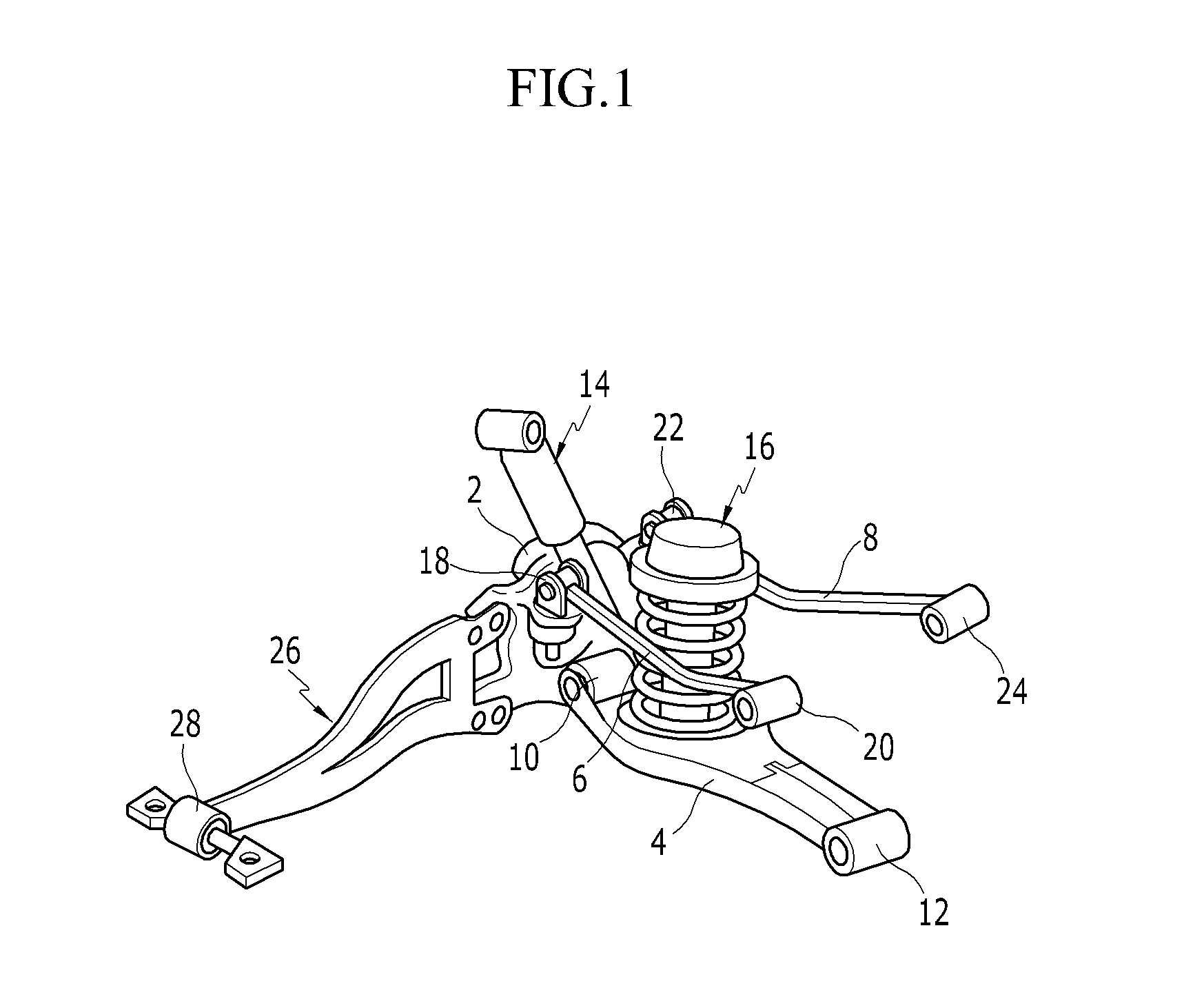
[0029]FIG. 1 is a perspective view of a multilink suspension system provided with an exemplary control arm according to the present invention.

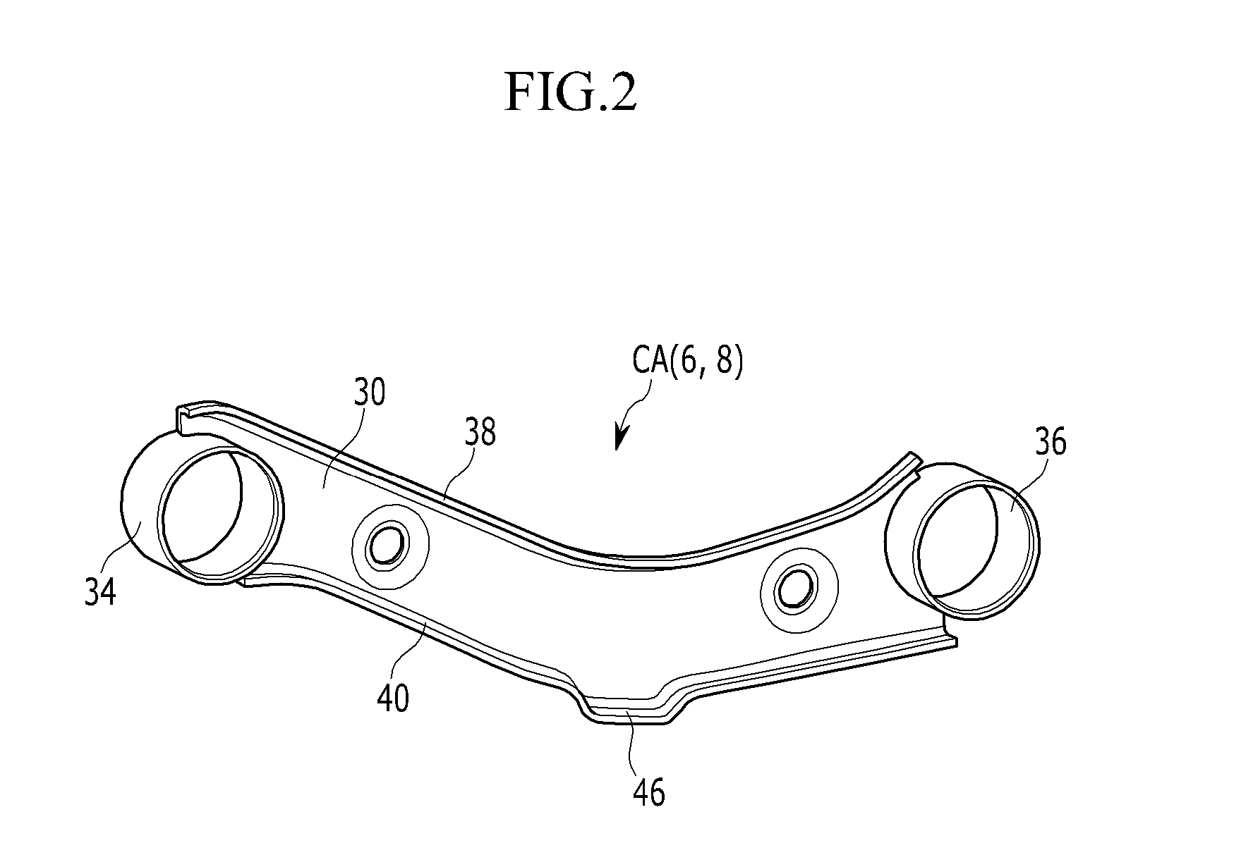
[0030]FIG. 2 is a perspective view of a front member forming an exemplary control arm according to the present invention.

[0031]FIG. 3 is a perspective view of a rear member forming an exemplary control arm according to the present invention.

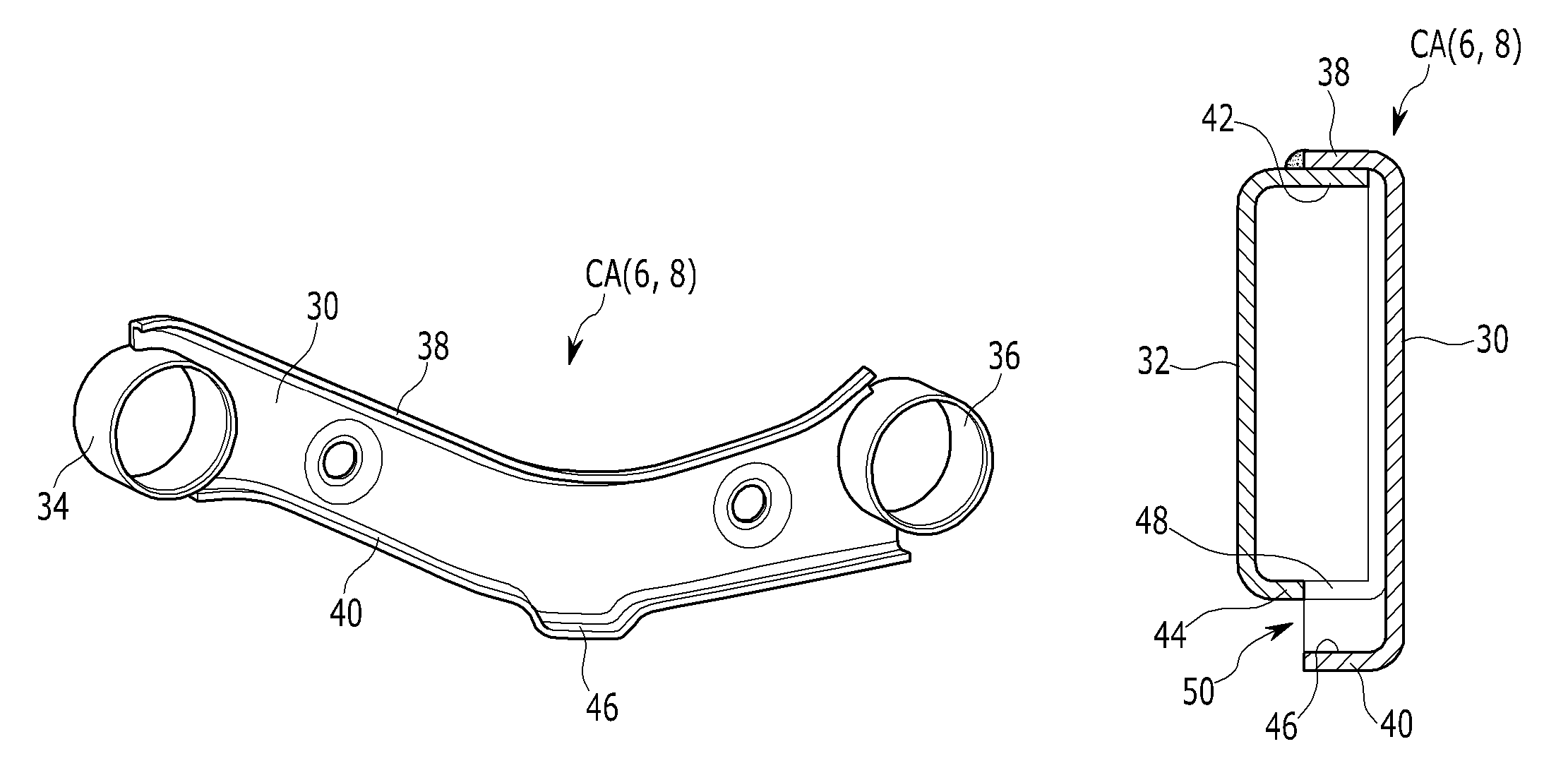
[0032]FIG. 4 is a perspective view of an exemplary control arm according to the present invention.

[0033]FIG. 5 is a cross-sectional view taken from a line I-I in FIG. 4.

[0034]FIG. 6 is a graph showing buckling compression stress of control arms according to the present invention and conventional arts.

[0035]FIG. 7 is a perspective view and a cross-sectional view of a conventional control arm without a drain hole.

[0036]FIG. 8 is a perspective view and a cross-sectional view of a conventional control ...


PUM


Abstract

A control arm may be formed by assembling front and rear members respectively having upper and lower flanges so as to have a tubular cross-section, and a bending portion may be formed by bending the lower flange of the front member downwardly such that a drain hole is formed by the bending portion protruded downwardly when the front and rear members are assembled.

Description

CROSS-REFERENCE TO RELATED APPLICATION[0001]The present application claims priority to Korean Patent Application No. 10-2009-0113510 filed in the Korean Intellectual Property Office on Nov. 23, 2009, the entire contents of which is incorporated herein for all purposes by this reference.BACKGROUND OF THE INVENTION[0002]1. Field of the Invention[0003]The present invention relates to a control arm applicable to a suspension system provided with multilinks. More particularly, the present invention relates to a control arm of a multilink suspension system control arm which can drain foreign materials input through a jig hole for manufacturing the control arm through a drain hole easily.[0004]2. Description of Related Art[0005]A suspension system for a vehicle is disposed between a vehicle body and a wheel, and connects two rigid bodies by using one or more links.[0006]An upward or downward load transmitted from a road to the wheel is supported by a spring and a hydraulic pressure shock a...

Claims


Application Information

Patent Timeline
Patent Type & Authority Patents(United States)
IPC IPC(8): B60G3/04B60G3/18
CPCB60G3/202B60G7/001B60G2206/8201B60G2206/722B60G2206/8103B60G2206/11B60G7/00B60G7/02
Inventor LEE, HOO GWANGPARK, JONG UN
Owner HYUNDAI MOTOR CO LTD
Why Eureka
Try Eureka