
Color difference signal IP conversion method

a conversion method and signal technology, applied in the direction of signal generators with optical-mechanical scanning, picture reproducers using projection devices, television systems, etc., to achieve the effect of suppressing the degradation of vertical bandwidth, reducing jaggy, and reducing jaggy

Inactive Publication Date: 2012-04-24
PANASONIC CORP
View PDF19 Cites 0 Cited by
  • Summary
  • Abstract
  • Description
  • Claims
  • Application Information

AI Technical Summary

Benefits of technology

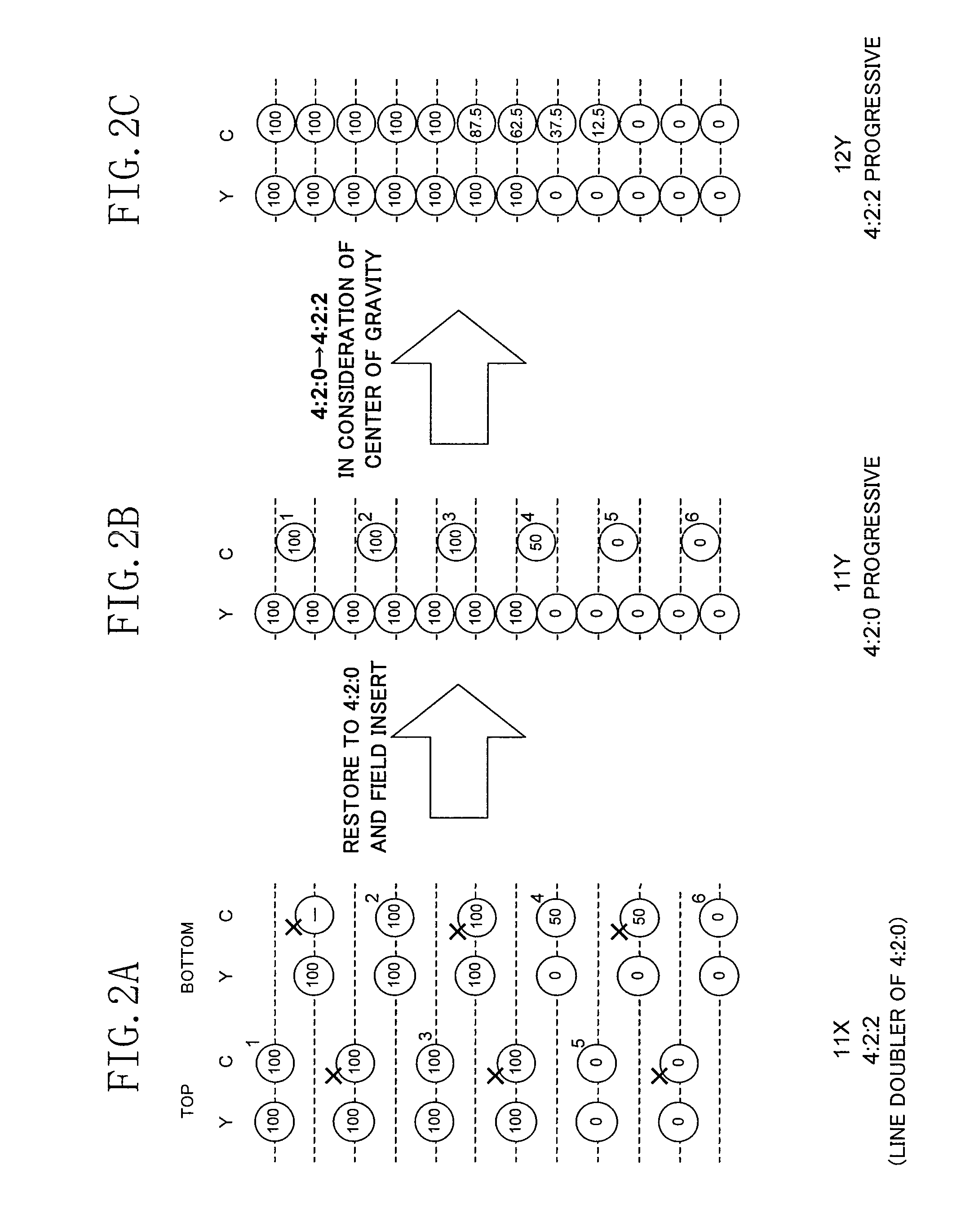
"The invention aims to provide a method for converting color-difference signals that reduces jaggy and maintains the initial frequency characteristic of a correct 4:2:2 signal. This is achieved by considering the origin of the input color-difference signal and performing appropriate conversion techniques based on that information."

Problems solved by technology

Therefore, there arises a problem when the inter-field interpolation is performed thereafter.

Method used


Image

  • Color difference signal IP conversion method
  • Color difference signal IP conversion method
  • Color difference signal IP conversion method

Examples


Embodiment Construction

[0081]A best mode for carrying out the invention will now be described with reference to the accompanying drawings. Although color-difference signals are classified into two kinds of signals, that is, an R-Y signal and a B-Y signal, they are described commonly as a color-difference signal C in the following description because they are similarly processed.

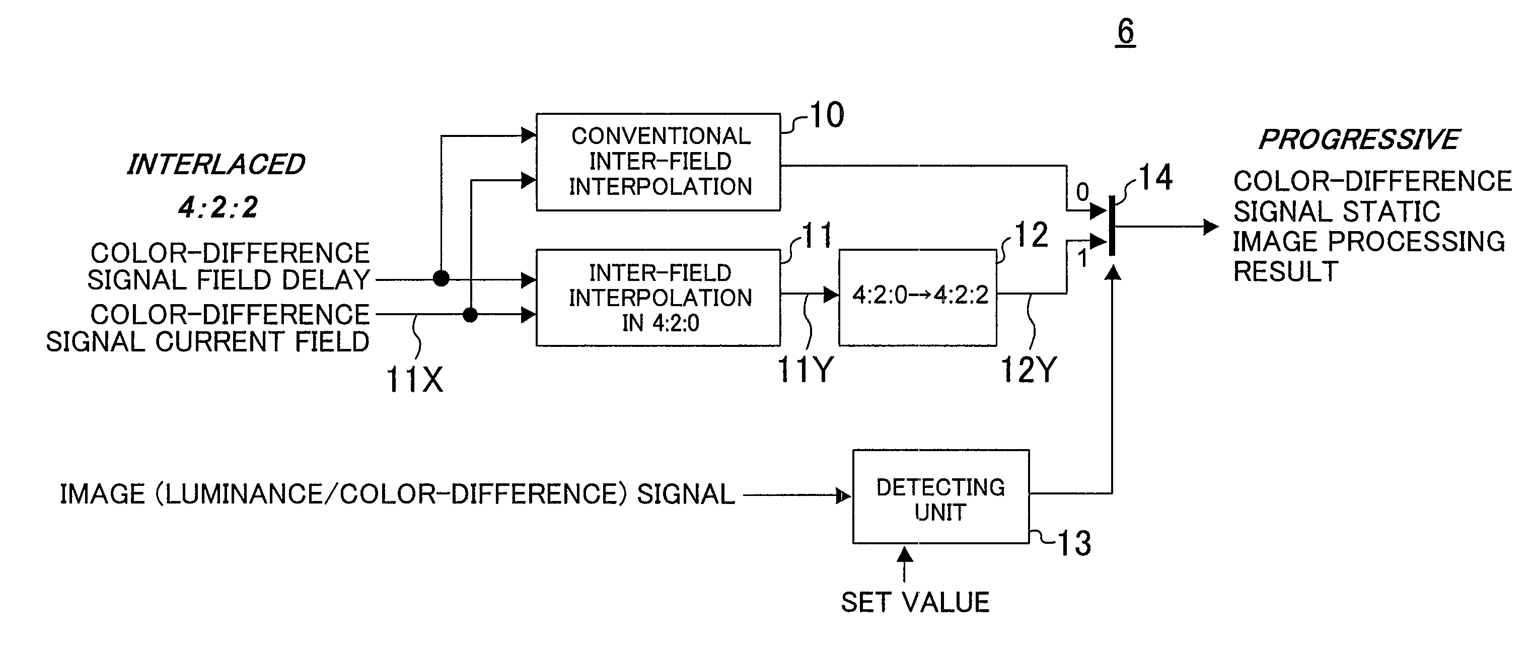
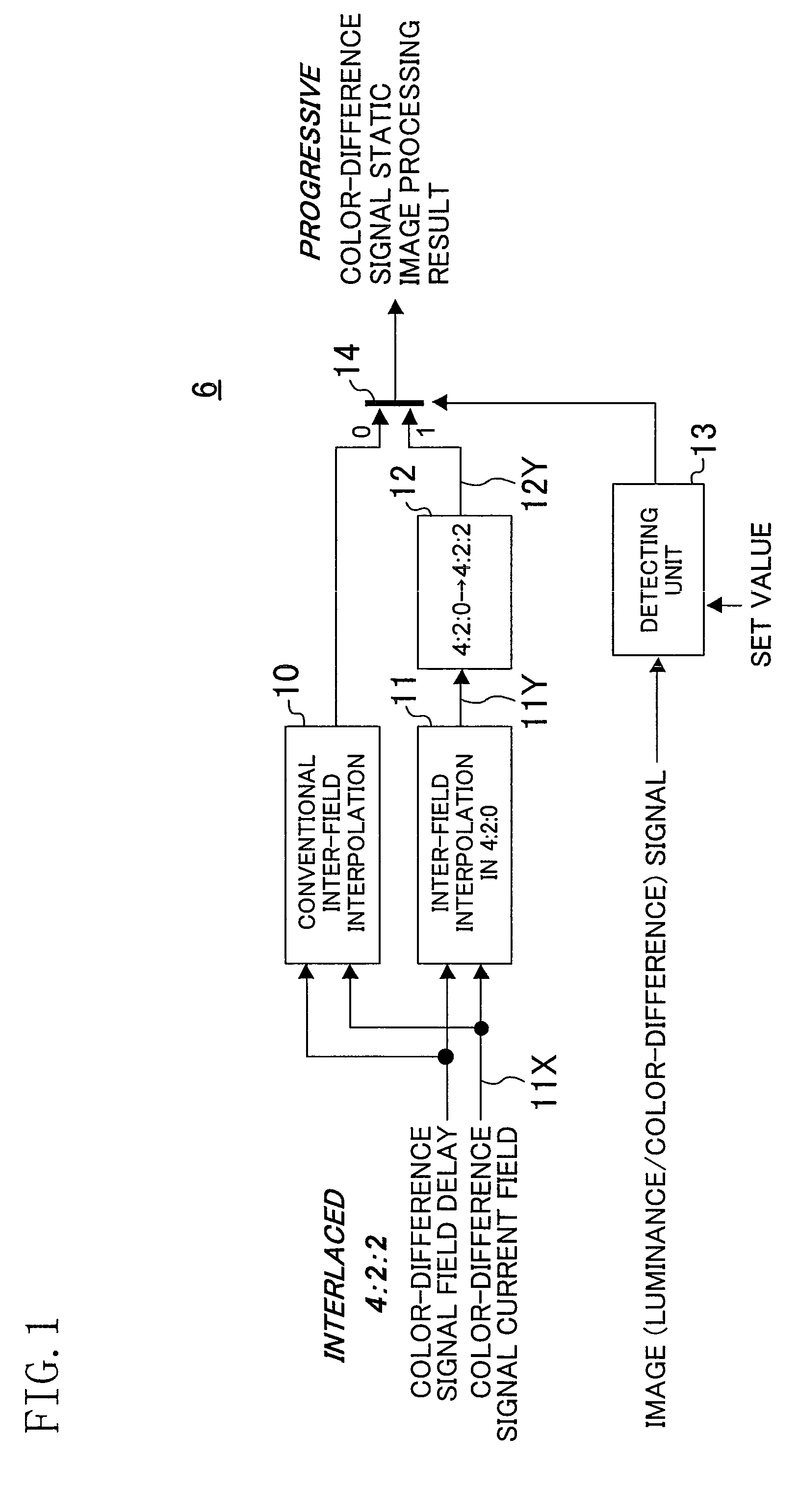
[0082]FIG. 1 shows a color-difference signal IP conversion static image processing unit of this invention. In FIG. 1, a reference numeral 6 denotes the color-difference signal IP conversion static image processing unit, which corresponds to a portion shown with the reference numeral 6 in the conventional example of FIG. 21. A reference numeral 10 denotes an inter-field interpolating unit corresponding to a conventional static image processing unit for a color-difference signal, a reference numeral 11 denotes a color-difference 4:2:0 inter-field interpolating unit, a reference numeral 12 denotes a color-difference intra-field line i...


PUM


Abstract

An output of a conventional color-difference inter-field interpolating unit (10) and an output obtained by a color-difference 4:2:0 inter-field interpolating unit (11) and a color-difference intra-field line interpolating unit (12) as a progressive signal through inter-field interpolation by changing a 4:2:2 color-difference signal into a 4:2:0 color-difference signal are switched by a color-difference static image processing method selecting / mixing unit (14) in accordance with an output or the like of a detecting unit (13) for detecting a characteristic of an image signal. Thus, it is possible to realize color-difference signal IP conversion static image processing in which degradation of a correct 4:2:2 color-difference signal is suppressed and jaggy is reduced with respect to a 4:2:2 color-difference signal obtained through interpolation of a 4:2:0 signal.

Description

RELATED APPLICATIONS[0001]This application is the U.S. National Phase under 35 U.S.C. §371 of International Application No. PCT / JP2007 / 062697, filed on Jun. 25, 2007, which in turn claims the benefit of Japanese Application No. 2006-260217, filed on Sep. 26, 2006, the disclosures of which Applications are incorporated by reference herein.TECHNICAL FIELD[0002]The present invention relates to a method for converting (IP converting) an image interlaced signal into a progressive signal, and more particularly, it relates to generation of a static image signal of a color-difference signal performed in motion adaptive IP conversion.BACKGROUND ART[0003]An image signal typically used in the systems such as NTSC, PAL, SECAM, hi-vision (1080i or the like) employs an interlace method in which alternate scanning lines are decimated to be transferred for forming an image of one frame with two fields, and when such an image signal is displayed on a display device employing a progressive scanning m...

Claims


Application Information

Patent Timeline
Patent Type & Authority Patents(United States)
IPC IPC(8): H04N7/01
CPCH04N7/012H04N7/0137
Inventor MIKI, YOICHIRO
Owner PANASONIC CORP
Learn More