
Illuminated helmet with programmable lamps and proximity sensor

a proximity sensor and programmable lamp technology, applied in the field of protective helmets, can solve the problems of not being protected by the helmet structure, not being able to provide additional intelligence, not being able to contain wiring within a module, etc., and achieve the effects of reducing the risk of lamp damage, minimizing thickness, and reducing overall mass

Inactive Publication Date: 2012-04-17
BARSEVENTY
View PDF15 Cites 38 Cited by
  • Summary
  • Abstract
  • Description
  • Claims
  • Application Information

AI Technical Summary

Benefits of technology

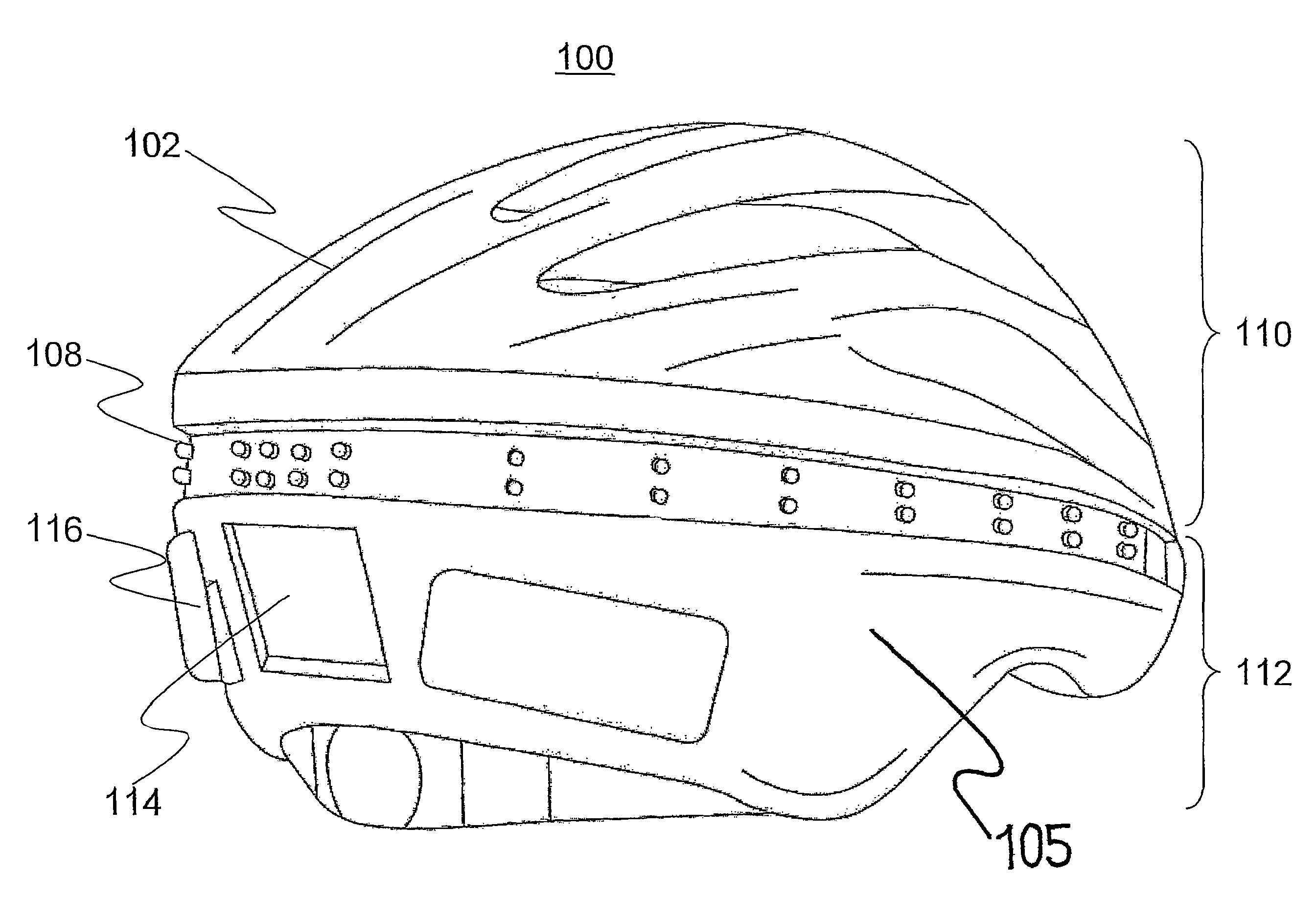
"The present invention provides an illuminated helmet with multiple lamps positioned in at least one recess in the helmet to reduce the risk of damage and injury during accidents. The helmet is built using surface mount technology to minimize thickness and mass. The lamps are arranged in a unique pattern to attract the attention of the human eye. The helmet also includes a proximity sensor mounted within the helmet that automatically activates the lamps when the helmet is worn by a user. The lamps are powered by a battery and the controller and lamps are mounted on the non-impact area of the helmet structure. The technical effects of this invention include improved safety and reliability of the lamps and helmet, reduced risk of injury from the components and lamps in an accident, and improved visibility and detection of the lamps."

Problems solved by technology

Wiring cannot be contained within a module inside the helmet, and is subject to mechanical stresses associated with using the chinstrap and holding the helmet to the user's head.
They are not capable of providing additional intelligence and are prone to failure.
A flat wiring cable is consequently exposed on the inside of the helmet and the outside of the helmet, and is not protected by helmet structure.
In addition, it is questionable from a safety stand point to place a foreign object directly against the head within the helmet.
The on / off switch cannot be operated with a minimal amount of attention.
The mass presented described lens also decreases the safety by creating a large mass which can be driven through the protective foam upon direct impact.
However, the prior art has not recognized the need for high reliability in illuminated helmets.
The designs are not adapted to fit into preexisting helmet designs.
Prior art systems have not been provided with integrated illumination systems into existing helmets without compromising their function or style.

Method used


Image

  • Illuminated helmet with programmable lamps and proximity sensor
  • Illuminated helmet with programmable lamps and proximity sensor
  • Illuminated helmet with programmable lamps and proximity sensor

Examples


Embodiment Construction

[0040]The object of the present invention is to provide an illuminated helmet with improved design, visibility and safety. The present invention provides an illuminated helmet with a plurality of lamps positioned in at least one recess in the helmet to reduce the risk of damage to the lamps and prevent the lamps from injuring a user during an accident. It is also build with surface mount technology (“SMT”) to minimize the thickness and reducing the overall mass; the two factors necessary to maximize safety by reducing the likelihood of the components being driven through the protective foam and into the head. The illuminated helmet also provides specific recesses for the lamps and other components located in a non-impact area of the helmet to further reduce the risk of injury from the components and lamps in an accident. Furthermore, the illuminated helmet provides a proximity sensor mounted within the helmet that lacks mechanical parts and automatically activates the lamps when the...


PUM


Abstract

An illuminated helmet with a plurality of lamps positioned in at least one recess, a controller to operate the lamps in a flashing pattern, and a proximity sensor to activate the controller and lamps upon detection of a user's head. The recesses for the lamps and other components are located in a non-impact area of the helmet. The lamps are arranged to be visible to a viewer from any angle, and the flashing patterns of the lamps are programmed to draw the attention of the human eye.

Description

PRIORITY CLAIM[0001]This application claims the benefit of priority to U.S. Provisional Application No. 60 / 746,721, filed May 8, 2006, entitled “Illuminated Helmet.”FIELD OF THE INVENTION[0002]The present invention relates to a protective helmet incorporating an illumination system, and more specifically a sensor-activated illumination system.BACKGROUND OF THE INVENTION[0003]Protective helmets are worn for protecting a wearer's head in performing many different activities. Activities may include construction work, bicycling, riding a motorcycle or participating in athletic activities. In addition to protecting a wearer's head from damaging impact, a helmet may serve the safety function, increasing the wearers visibility under all conditions; day or night, rain or fog. Reflectors have been used as a low-cost visibility aid. However, reflectors are passive devices. Their efficacy is affected by the nature of the illumination source, the angle of incidence and the position of a viewer ...

Claims


Application Information

Patent Timeline
Patent Type & Authority Patents(United States)
IPC IPC(8): F21V21/084
CPCA42B3/0433A42B3/044Y10S362/802
Inventor HUSS, STEPHEN JAMESNIELSEN, BRYAN JOSEPH
Owner BARSEVENTY
Learn More