Device for gravity-bending glass on several support moulds with controlled transition between moulds

a technology of gravity bending and support moulds, which is applied in the direction of glass blowing apparatus, glass making apparatus, glass shaping apparatus, etc., can solve the problems of lateral displacement of sheets, lower reproducibility of final glazing, or even marking of glazing, etc., and achieve the effect of reducing the risk of glass being marked by the support and reproducibility

Active Publication Date: 2012-04-17
SAINT-GOBAIN GLASS FRANCE
View PDF7 Cites 17 Cited by
  • Summary
  • Abstract
  • Description
  • Claims
  • Application Information

AI Technical Summary

Benefits of technology

[0005]The change in shape of the support, such as for example on passing from one support to another, is a tricky step in so far as it is necessary for the glass not to jump or move laterally at the moment of the change in shape of the support. Now, this change in shape of the support may be relatively abrupt, sometimes resulting in a lateral displacement of the sheet and therefore a lower reproducibility of the final glazing, or even marking of the glazing. The present invention remedies this problem by allowing a gentle change in the shape of the support that is supporting the glass, especially a gentle transition from one support to another if the change in shape involves at least two supports. The glass therefore always remains in the correct position and the manufacturing batches are more uniform. Moreover, the risk of the glass being marked by the support(s) is reduced. The present invention applies to single-support devices, the shape of the support varying during bending, or to multi-support devices comprising two or three, or even more, supports. In addition, the device according to the invention may also combine substitution of at least two supports and variation in the shape of one of the supports.
[0018]To give an example, the means of controlling the rate of shape change (such as the substitution of one support with another) may comprise the combination of a horizontal bar linked to one of the supports, of a part with an inclined surface and of a means of moving said part with an inclined surface horizontally, it being possible for the inclined surface to support said horizontal bar so that the horizontal movement of the part with an inclined surface is reflected in a vertical movement of the support linked to the horizontal bar. Thus, the horizontal bar linked to one of the supports slides on the inclined surface and moves vertically as a direct consequence of the inclination of said surface. The support or support part linked to the bar can therefore be raised or lowered by a simple horizontal displacement of the part with an inclined surface. By controlling the rate of horizontal displacement of the part with an inclined surface, the speed of vertical displacement of the support bearing the horizontal bar is controlled.
[0024]In one particularly suitable embodiment, the relative vertical movement of the two supports is provided by lowering the first support, the second remaining stationary, at a constant height, throughout the bending. The force causing the lowering may preferably be quite simply the force of gravity. In this case, the first support is initially locked in the high position during the first bending phase and is unlocked at the opportune moment for freeing the first support and allowing the force of gravity to pull it downward. A means of controlling and slowing down the drop of the first support softens the transition from the first to the second support. This slowing-down means may be the combination of a horizontal bar fastened to the first support and of a part with the inclined surface passing beneath the bar, coming into contact with it and moving horizontally. The part with the inclined surface, via its contact with the horizontal bar linked to the first support, moderates and contains this force of gravity in order to ensure that the first support is lowered in a controlled and progressive manner.
[0030]The assembly according to the invention allows a glass sheet or several (especially two) superposed glass sheets, generally separated from each other by a powder well known to those skilled in the art for preventing them from sticking, to be bent. In particular, several glass sheets are bent simultaneously when it is desired thereafter to assembly them as laminated glazing. Simultaneous bending confers better identity of the bending of the various sheets that have to be joined together in the same glazing.
[0032]However, the reverse operation may be carried out, by raising the second support and leaving the first one at a fixed height. The combination of lowering one support and raising the other is possible.

Problems solved by technology

The change in shape of the support, such as for example on passing from one support to another, is a tricky step in so far as it is necessary for the glass not to jump or move laterally at the moment of the change in shape of the support.
Now, this change in shape of the support may be relatively abrupt, sometimes resulting in a lateral displacement of the sheet and therefore a lower reproducibility of the final glazing, or even marking of the glazing.

Method used


Image

  • Device for gravity-bending glass on several support moulds with controlled transition between moulds
  • Device for gravity-bending glass on several support moulds with controlled transition between moulds
  • Device for gravity-bending glass on several support moulds with controlled transition between moulds

Examples


Embodiment Construction

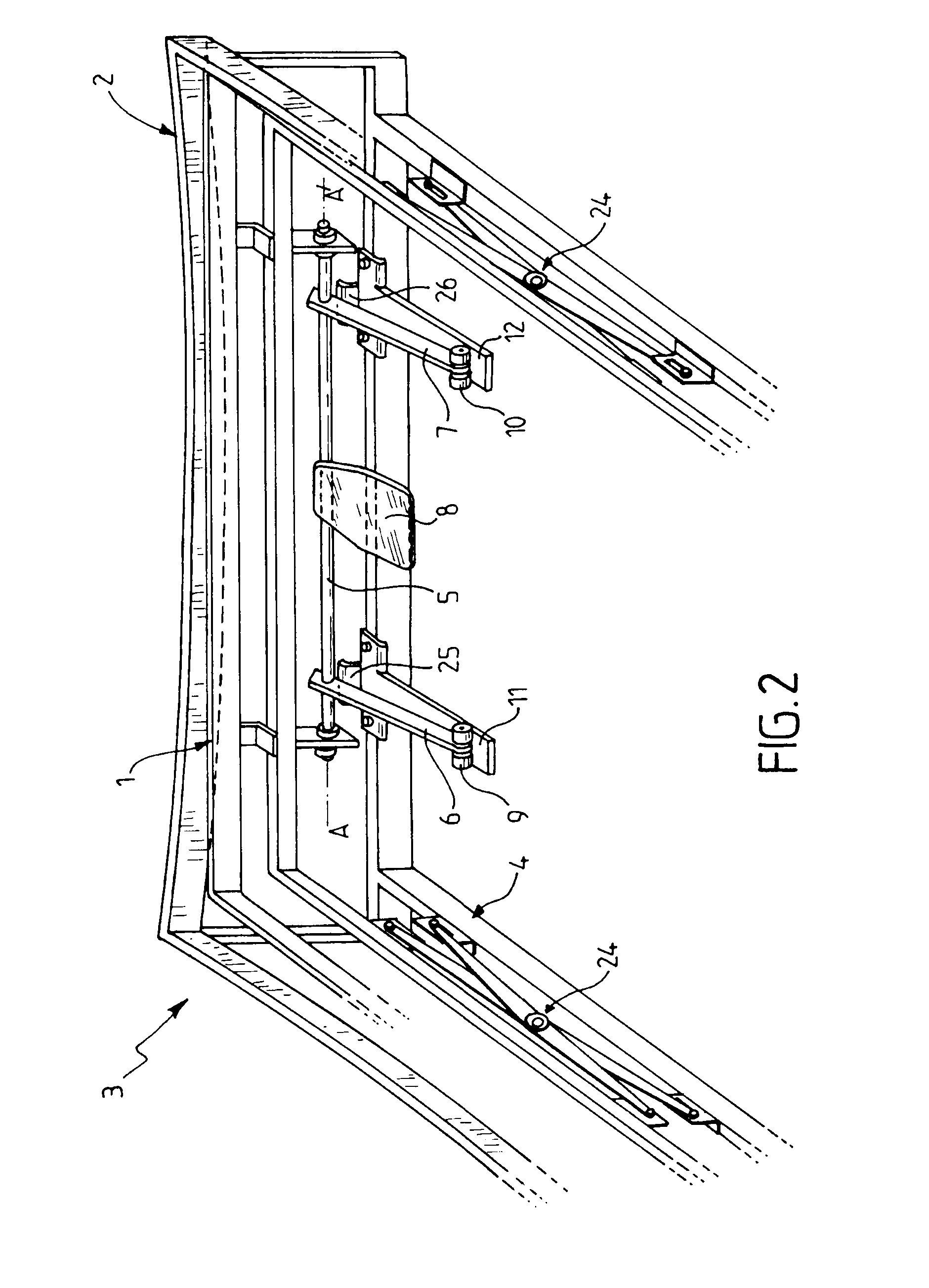
[0049]FIG. 1 shows a bending assembly 3 comprising a first support 1 and a second support 2. This assembly is shown in the state corresponding to the first bending phase, that is to say the first support is in an upper position for carrying the glass sheet placed horizontally thereon. The second support 2 is in a lower, standby, position. This second support is fastened to the framework supporting the assembly and does not move throughout the bending operation. This figure shows part of the system for initiating the replacement of the first support with the second support in the upper position for supporting the glass. This part of the system is fixedly linked to the first support and comprises a horizontal bar 5 (a different bar from that used to control the rate of lowering of the first support) which can rotate about its axis AA′, a pad 8 fastened to this bar 5 being able to receive a thrust via the outside of the assembly (and therefore via the concealed side of the pad shown in...


PUM

PropertyMeasurementUnit
bending temperatureaaaaaaaaaa
temperaturesaaaaaaaaaa
gravity bendingaaaaaaaaaa

Abstract

A device for gravity bending of at least one glass sheet supported by at least one support forming part of a bending assembly, plural supports supporting the sheet during bending. The device includes a drive system for changing the shape of the support, the drive system controlling the rate of the change. A method of bending glass sheets utilizes the device.

Description

BACKGROUND OF THE INVENTION[0001]I. Field of the Invention[0002]The invention relates to the gravity bending of glass sheets on a multiplicity of supports.[0003]II. Description of Related Art[0004]The gravity bending of glass sheets is well known. This bending may be carried out on a simple support, of the frame or skeleton type, the geometry of which does not vary during the bending. However, if it is desired to obtain particular, especially particularly pronounced, amounts of bending, it is useful to carry out the bending on supports whose geometry varies during bending. Thus, supports of the hinged skeleton type having two lateral parts that fold up during bending are known (see U.S. Pat. No. 4,286,980 or U.S. Pat. No. 5,167,689). Bending assemblies comprising two peripheral supports for the glass sheets in which one entirely substitutes for the other during bending are also known. Such assemblies have been described in EP 448 447 and EP 705 798. Finally, WO 2004 / 103922 teaches t...

Claims


Application Information

Patent Timeline
Patent Type & Authority Patents(United States)
IPC IPC(8): C03B23/025C03B23/023
CPCC03B23/027C03B23/025
Inventor MACHURA, CHRISTOPHECHIAPPETTA, SERGE
Owner SAINT-GOBAIN GLASS FRANCE
Why Eureka
Try Eureka