Operating apparatus

a technology of operating apparatus and control system, which is applied in the direction of motor/generator/converter stopper, dynamo-electric converter control, instruments, etc., can solve the problems that the control system described above cannot achieve both high-speed and high-speed, and achieve the effect of reducing the vibration of the main body and high-speed positioning of the movable member

Active Publication Date: 2012-04-10
NAGOYA INSTITUTE OF TECHNOLOGY +1
View PDF9 Cites 0 Cited by
  • Summary
  • Abstract
  • Description
  • Claims
  • Application Information

AI Technical Summary

Benefits of technology

[0009]In the operating apparatus, there are cases where a control quantity (especially that of an object whose vibration is to be damped or reduced) is not fed back, or feedback information constitutes only a part of a control quantity. In a case where it is impossible to measure or observe a control quantity, it was conventionally practiced to tune or adjust a feedforward compensator or a position command so as to satisfy the required specifications. However, in this case a feedback control is not at all applied to the unobservable control quantity, which is a limitation of such a countermeasure.
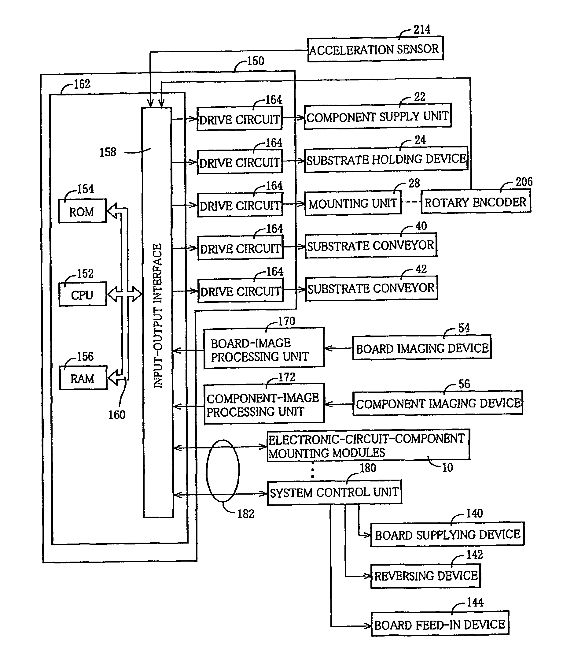
[0010]On the other hand, according to the control unit of the present operating apparatus, the information related to the acceleration of the main body that is obtained by the acceleration-information acquiring device is not directly or without processing fed back to the operation command to the drive source, but the difference between this information and the acceleration command, which is the output of the third feedforward compensator which receives the position command from the position command portion, is fed back to the operation command to the drive source, in order to actively damp the vibration of the main body.
[0011]Thus, it is enabled to achieve high-speed positioning of the movable member while reducing vibration of the main body.MODES OF THE INVENTION
[0012]There will be described by way of examples modes of inventions recognized to be claimable by the present applicant. The inventions may be hereinafter referred to as “claimable inventions”, and include at least the invention as defined in the appended claims, which may be referred to as “the invention” or “the invention of the present application”. However, the inventions may further include an invention of a concept subordinate or superordinate to the concept of the invention of the present application, and / or an invention of a concept different from the concept of the invention of the present application. The modes are numbered like the appended claims and depend from another mode or modes, where appropriate, for easy understanding of the claimable inventions. It is to be understood that combinations of features of the claimable inventions are not limited to those of the following modes. That is, the claimable inventions are to be construed by taking account of the description following each mode, the description of the embodiments, the related art, and others, and as long as the claimable inventions are constructed in this way, any one of the following modes may be implemented with one or more features added, or one or more of a plurality of features included in any one of the following modes are not necessarily provided all together.
[0014]a movable member which is movable relative to the main body;
[0015]a drive unit which includes a drive source and moves the movable member relative to the main body; and

Problems solved by technology

However, in some cases the control systems described above cannot sufficiently achieve both the high-speed positioning of the movable member and the reduction of vibration of the movable member, and improvement thereon were requested.

Method used


Image

  • Operating apparatus
  • Operating apparatus
  • Operating apparatus

Examples


Embodiment Construction

[0012]There will be described by way of examples modes of inventions recognized to be claimable by the present applicant. The inventions may be hereinafter referred to as “claimable inventions”, and include at least the invention as defined in the appended claims, which may be referred to as “the invention” or “the invention of the present application”. However, the inventions may further include an invention of a concept subordinate or superordinate to the concept of the invention of the present application, and / or an invention of a concept different from the concept of the invention of the present application. The modes are numbered like the appended claims and depend from another mode or modes, where appropriate, for easy understanding of the claimable inventions. It is to be understood that combinations of features of the claimable inventions are not limited to those of the following modes. That is, the claimable inventions are to be construed by taking account of the descriptio...


PUM


Abstract

An operating apparatus including a main body, a movable member, a drive unit having a drive source, and a control unit controlling the drive source to control the position of the movable member relative to the main body. The control unit including a position control system and an acceleration control system. The position control system including a position command portion, a first feedforward compensator outputting a first operation command to the drive source, a second feedforward compensator, a positional-information acquiring device obtaining information related to the position of the movable member, and a first feedback compensator outputting a second operation command to the drive source. The acceleration control system including an acceleration-information acquiring device obtaining information related to an acceleration of the main body, a third feedforward compensator, a second feedback compensator outputting a third operation command to the drive source.

Description

CROSS REFERENCE TO RELATED APPLICATION[0001]The present application claims priority from Japanese Patent Application No. 2008-057635, which was filed on Mar. 7, 2008, the disclosure of which is herein incorporated by reference in its entirety.BACKGROUND OF THE INVENTION[0002]1. Field of the Invention[0003]The present invention relates to an operating apparatus including a main body, a movable member held such that the movable member is movable relative to the main body, and a drive unit that moves the movable member relative to the main body. In particular, the invention relates to a technique for enabling to position the movable member at high speed and reduce vibration of the main body at the same time.[0004]2. Description of Related Art[0005]For the operating apparatus of this kind, there have been proposed techniques enabling high-speed positioning of a movable member as well as reducing vibration of a main body, as disclosed in JP-A-5-250041, JP-A-6-151272, and JPA-2004-240609,...

Claims


Application Information

Patent Timeline
Patent Type & Authority Patents(United States)
IPC IPC(8): H02P1/00
CPCG05B5/01
Inventor SAWARAGI, HIROSHINAGIRI, KEISUKEKAWAI, TAKAYOSHIMATSUI, NOBUYUKIIWASAKI, MAKOTO
Owner NAGOYA INSTITUTE OF TECHNOLOGY
Why Eureka
Try Eureka