
Hammer head with recessed traction striking surface

a traction striking surface and hammer head technology, applied in the field of hand tools, can solve the problems of reducing nail driving efficiency and risk of flying projectiles, and achieve the effect of durable traction and greater resistance to wear

Active Publication Date: 2012-03-27
SPENCER STEPHEN M +1
View PDF17 Cites 20 Cited by
  • Summary
  • Abstract
  • Description
  • Claims
  • Application Information

AI Technical Summary

Benefits of technology

[0016]Advantageously, the disk is fitted in a hammer head made of titanium or titanium alloy, replacing the titanium striking surface. This embodiment provides the light weight advantages of titanium hammer heads, while providing a much longer usable life of the traction striking surface.
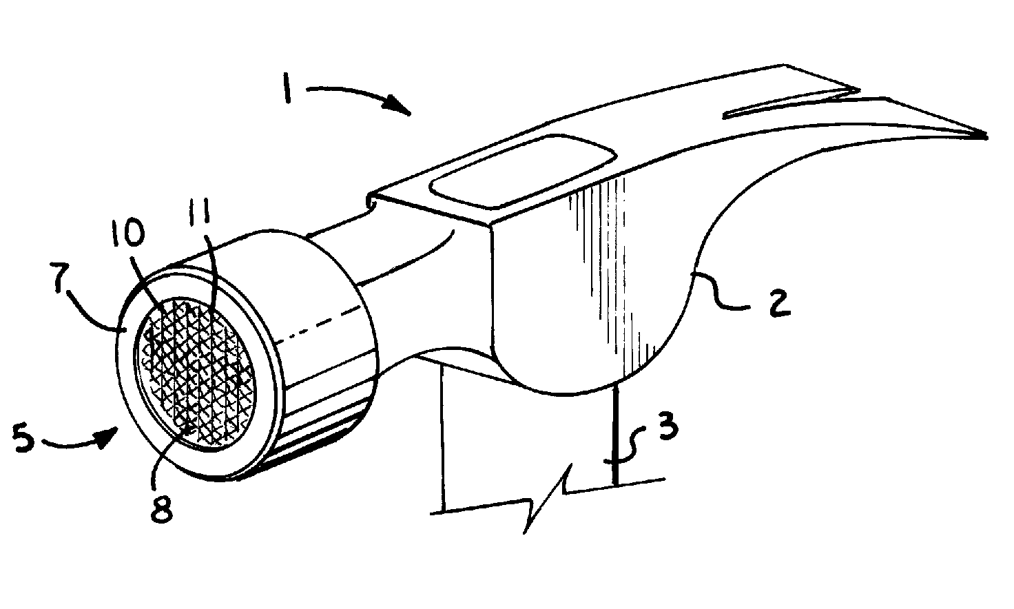
[0018]As mentioned above, in accordance with a preferred embodiment, the disk is placed in the face of a hammer head in a way that it is recessed from the plane of the striking surface about 1 / 16 of an inch, leaving the forward-most plane of the striking surface as a smooth rim (for example, an annulus) about ¼ of an inch wide around the outside perimeter of the face of the hammer head. This embodiment allows only the smooth portion of the striking surface to contact the material that the nail is being driven into, eliminating the damaging waffle pattern indentations caused by misdirected or glancing blows, or the final blow that sets the head of the nail flush or beyond the surface of the material the nail is being driven into. This embodiment also eliminates the need for a second, smooth faced hammer for use with finished materials. This embodiment is also advantageous in concrete work, where a hammer is used consecutively to drive both nails and pins used to hold forms together.
[0019]In the case of driving wedge pins in form work, a traction surface on the striking face is worn down quickly, while excessively damaging the reusable pins. The application of the recessed traction surface allows the use of the same hammer in driving wedge pins and nails for fastening wood members, while reducing wear on both the hammer head and reusable pins considerably.

Problems solved by technology

In addition, a further drawback heretofore is that the waffle traction surface of a framing hammer typically wears smooth quickly with regular use, reducing nail driving efficiency and causing the risk of flying projectiles as pieces of the traction surface tend to break off as the hammer is striking nails.
This is especially problematic with titanium hammer heads, but nonetheless prevalent with all framing hammers.

Method used


Image

  • Hammer head with recessed traction striking surface
  • Hammer head with recessed traction striking surface
  • Hammer head with recessed traction striking surface

Examples


Embodiment Construction

[0029]A hammer structure is disclosed which includes a traction surface provided on a centrally located region of a striking face of the head of the hammer wherein the portion of the striking face surrounding the traction surface is relatively smooth. The centrally located region is preferably comprised of a harder material than a remainder of the hammer head, including the region surrounding the traction surface. The traction surface is preferably recessed relative to the surrounding hammer face, such that wear to this working surface is inhibited.

[0030]A first embodiment of the invention is depicted in FIG. 1, in which a hammer 1 includes a hammer head or hammer head body 2 carried on a handle 3. A forward portion of the hammer head 2 includes a striking face 5 generally arranged in a striking plane extending perpendicular to a striking (swing) direction of the hammer 1 during use. The striking face 5 of the hammer head 2 includes a peripheral region or surface 7 and a central, re...


PUM


Abstract

A hammer head includes a centrally located traction surface surrounded by a peripheral striking face. The portion of the hammer head forming the traction surface is comprised of a harder material than the surrounding portion of the hammer head, such that wear to the traction surface is inhibited. The centrally located region may be formed as a separate disk with a knurled outer surface that is press fit into a cavity formed in the hammer head main body. The traction surface is preferably recessed relative to the surrounding portion of the hammer head but may also extend flush therewith.

Description

CROSS-REFERENCE TO RELATED APPLICATIONS[0001]This application claims the benefit of the prior filed, co-pending provisional application Ser. No. 61 / 199,125, filed Nov. 13, 2008, which is hereby incorporated by reference herein.BACKGROUND OF THE INVENTION[0002]The present invention relates to hand tools, and more particularly, to a traction striking surface feature provided on the head of a framing hammer, accommodating a demand for a more resilient and wear resistant traction surface, as well as addressing the need for two different hammers for rough framing and finish trim work, thereby improving the versatility of claw hammers.[0003]Hand held striking tools, such as claw hammers, have been used for centuries by people performing a great variety of tasks associated with carpentry. Typically, steel and titanium framing and finish hammers are used to deliver a striking force to drive nails into wood and other materials. The claw of a hammer is used, for example, to pull nails from sa...

Claims


Application Information

Patent Timeline
Patent Type & Authority Patents(United States)
IPC IPC(8): B25D1/00
CPCB25D1/00B25D1/02
Inventor SPENCER, STEPHEN M.SPENCER, RICHARD A.
Owner SPENCER STEPHEN M
Learn More