
System and method for streetlight monitoring diagnostics

a streetlight and diagnostic technology, applied in the field of streetlight monitoring, can solve the problems of significant increase in the operating cost of the outdoor lighting system, maintenance and repair problems, and significant cost associated with hiring qualified maintenance personnel and buying equipmen

Active Publication Date: 2012-03-20
ABL IP HLDG
View PDF400 Cites 85 Cited by
  • Summary
  • Abstract
  • Description
  • Claims
  • Application Information

AI Technical Summary

Problems solved by technology

This method of operating outdoor lights results in many lights being on when they are not needed, and it significantly increases outdoor lighting system operating costs.
The use of conventional photo-controls to control outdoor lights (luminaires) also leads to maintenance and repair issues.
There are significant costs associated with hiring qualified maintenance personnel and buying equipment such as, for example, special maintenance vehicles required to access light fixtures for replacing lamps and servicing electrical components.
These high costs limit how many lights can be repaired or serviced on any given day and force many light system operators to maintain their outdoor lights on an as needed basis (i.e., only when they are notified of an inoperable light).
Understandably, this maintenance methodology is highly inefficient because it ties up resources as crews and equipment randomly travel to failed, geographically dispersed outdoor lights.

Method used


Image

  • System and method for streetlight monitoring diagnostics
  • System and method for streetlight monitoring diagnostics
  • System and method for streetlight monitoring diagnostics

Examples


Embodiment Construction

[0025]The present invention will now be described more fully hereinafter with reference to the accompanying figures, in which like numerals indicate like elements throughout the several drawings. Some, but not all embodiments of the invention are described. Indeed, these inventions may be embodied in many different forms and should not be construed as limited to the embodiments set forth herein; rather, these embodiments are provided so that this disclosure will satisfy applicable legal requirements, be thorough and complete, and will fully convey the scope of the invention to those skilled in the art.

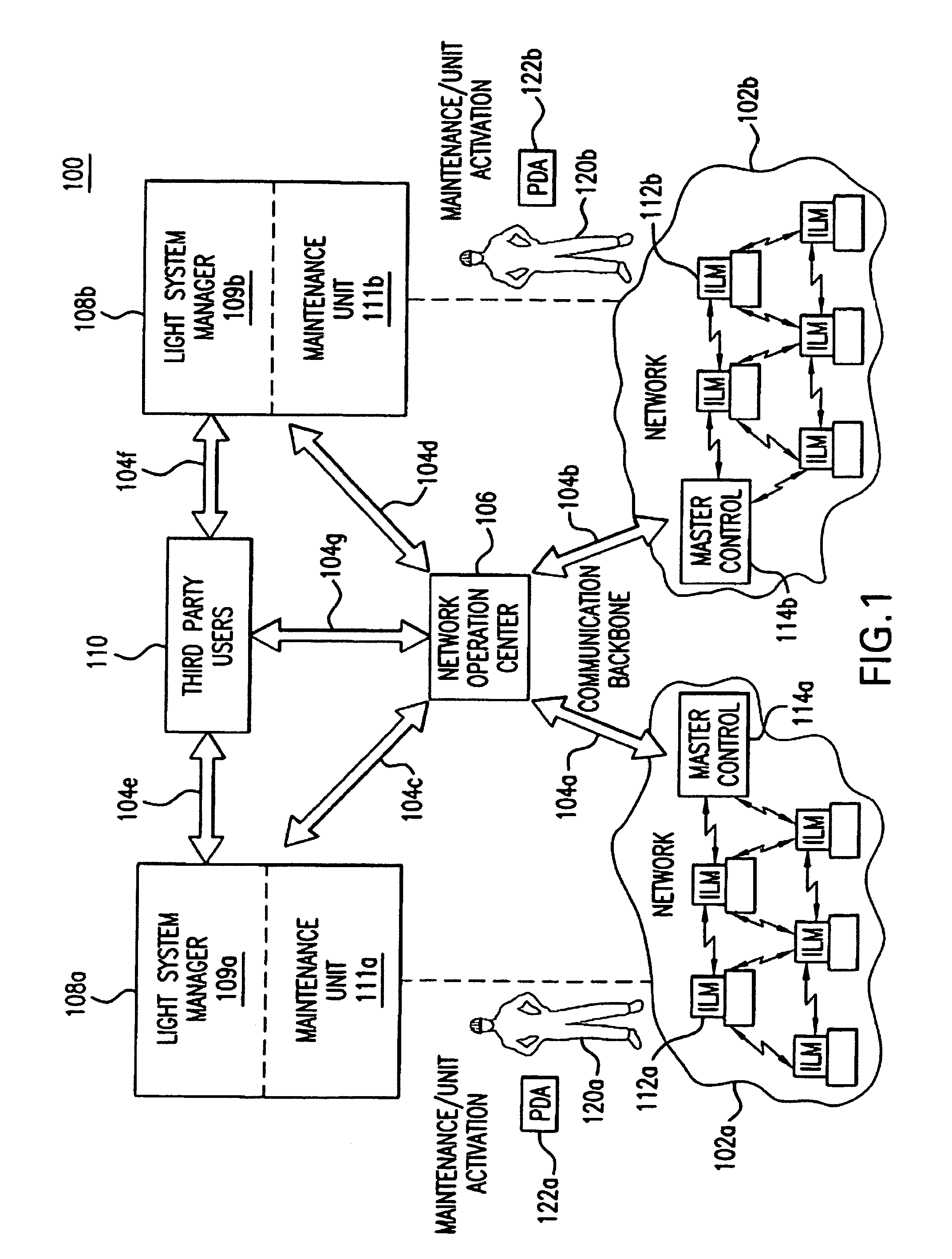
[0026]FIG. 1 illustrates a light management system 100 having networked intelligent luminaire managers 112 according to an example embodiment of the invention. As illustrated in FIG. 1, the light management system 100 includes networks 102a and 102b, a network operation center 106, light system owner / operators 108a and 108b, and third-party users 110. These subsystems of system 100 are...


PUM


Abstract

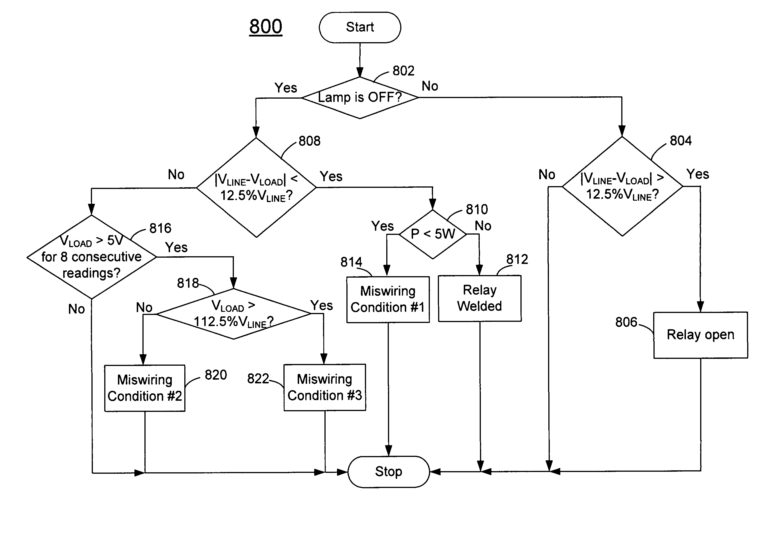
One or more example diagnostics may be implemented as part of an intelligent luminaire manager or other radio frequency (RF) device that is in communication with an equipment or fixture such as a luminaire. Example diagnostics can determine a status such as a fixture malfunction, a cycling condition, a miswiring configuration, or another condition. The determined status can be wirelessly transmitted from the intelligent luminaire manager or other radio frequency device to a network server via a network. The network may be a network of intelligent luminaire managers and / or RF devices.

Description

RELATED APPLICATION[0001]The present application claims priority to U.S. Provisional Application Ser. No. 61 / 031,865, filed Feb. 27, 2008, and entitled “STREET LIGHT MONITORING SYSTEM,” which is hereby incorporated in its entirety by reference.FIELD OF THE INVENTION[0002]Aspects of the present invention relate generally to streetlight monitoring, and more particularly to systems and methods for streetlight monitoring diagnostics.BACKGROUND OF THE INVENTION[0003]It is estimated that there are more than 60 million outdoor lights in the United States autonomously controlled by conventional photo-controls. These outdoor lights, when properly working, simply react to ambient light conditions, for example, to turn-on at dusk and turn-off at dawn. This method of operating outdoor lights results in many lights being on when they are not needed, and it significantly increases outdoor lighting system operating costs.[0004]The use of conventional photo-controls to control outdoor lights (lumin...

Claims


Application Information

Patent Timeline
Patent Type & Authority Patents(United States)
IPC IPC(8): G01R31/00H05B37/00
CPCG01R31/44H05B37/034Y02B20/48H05B47/22H05B47/19Y02B20/40
Inventor WALTERS, JEFFDOROGI, MICHAELZIGOVSZKI, SZABOLCSCRISTIAN, VOICUTICUS, ION
Owner ABL IP HLDG
Learn More