
Long ultrasonic cutting blade formed of laminated smaller blades

a technology of ultrasonic cutting blades and laminated blades, which is applied in the field of ultrasonic surgical instruments, can solve the problems of reducing the efficiency of the blade, limiting and reducing the effective length of the blad

Inactive Publication Date: 2012-03-20
TYCO HEALTHCARE GRP LP
View PDF10 Cites 7 Cited by
  • Summary
  • Abstract
  • Description
  • Claims
  • Application Information

AI Technical Summary

Benefits of technology

The patent describes an ultrasonic surgical instrument with a special end effector that can be used for tissue dissection, cutting, coagulation, ligation, and hemostasis. The end effector has multiple resonant members that vibrate along their length and an operating surface to effect tissue manipulation. The displacement curve of the first resonant member is offset relative to the displacement curve of the second resonant member. The resonant members may be a laminate or a frame with a resonant structure that includes the operating surface. The instrument also has a manipulatable structure and a body portion with a distal end and multiple transducers. The technical effects of this invention include improved tissue manipulation with reduced bleeding and improved precision and control during surgical procedures.

Problems solved by technology

The sinusoidal motion of the vibrations of the blade is a limiting factor that constrains the effective length of the blade.
The areas of no motion decrease the effective length of the blade, decreasing efficiency of the blade, and thus undesirably increasing the time needed to complete the surgical procedure.
Furthermore, there are large variations in amplitude along the length of the blade due to the sinusoidal nature of the oscillations, resulting in inconsistent behavior of the blade, and a lack of uniform operative results along the length of the blade.

Method used


Image

  • Long ultrasonic cutting blade formed of laminated smaller blades
  • Long ultrasonic cutting blade formed of laminated smaller blades
  • Long ultrasonic cutting blade formed of laminated smaller blades

Examples


Embodiment Construction

[0033]An ultrasonic surgical instrument for effecting a surgical procedure at an end effector is provided, in which the end effector includes an array of staggered elements, where the staggering is configured so that displacement curves associated with displacement of each element are offset with respect to one another for collectively maximizing effective operation and consistency of operation of the array of elements.

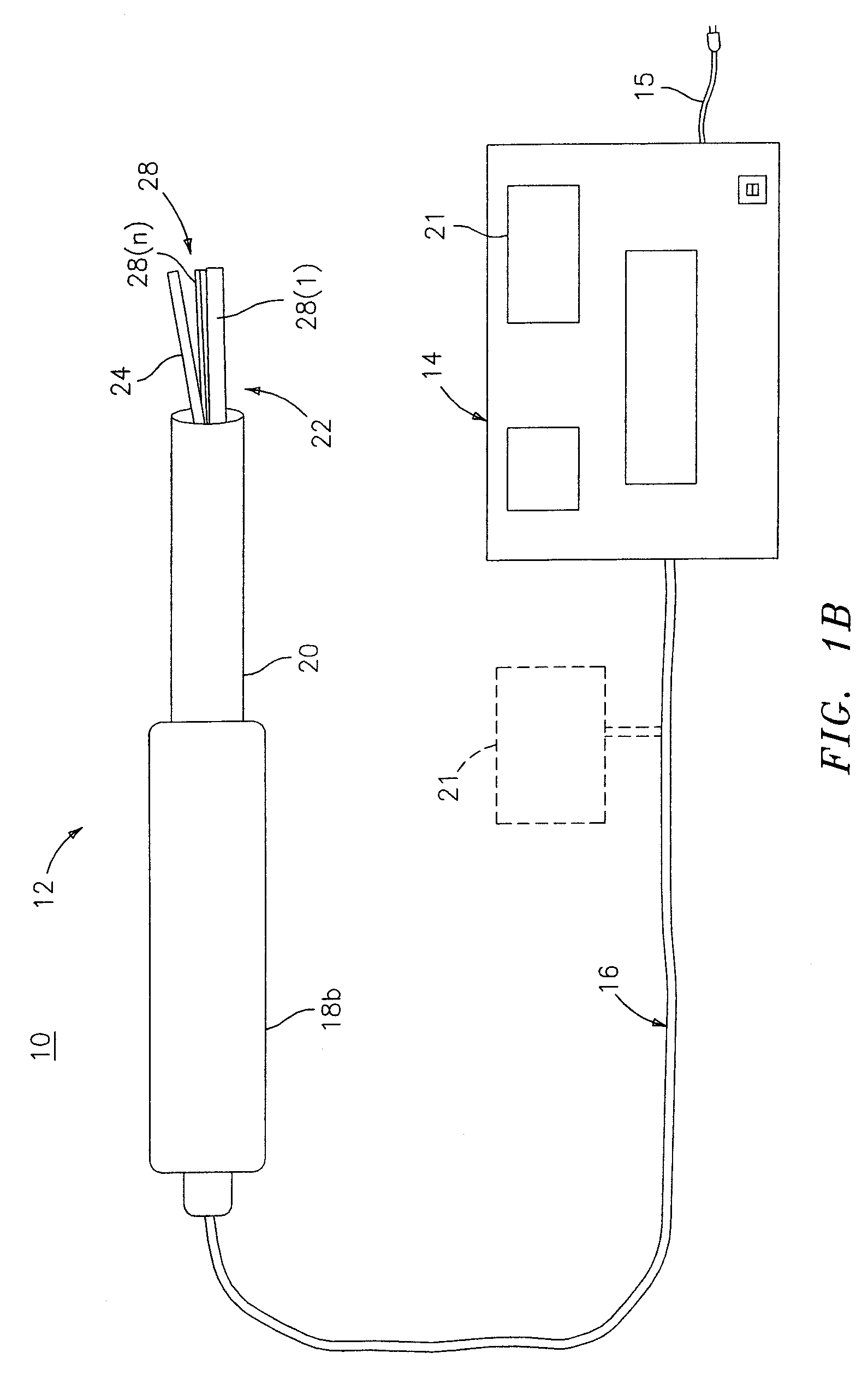
[0034]Preferred embodiments of the presently disclosed ultrasonic surgical instrument will now be described in detail with reference to the drawings, in which like reference numerals designate identical or corresponding elements in each of the several views. FIGS. 1A and 1B illustrate schematic views of first and second embodiments, respectively, of exemplary ultrasonic surgical system shown generally as 10. System 10 includes an ultrasonic instrument 12, a control module 14 and conductive cable 16 interconnecting ultrasonic instrument 12 to control module 14. Ultraso...


PUM


Abstract

An end effector of an ultrasonic surgical instrument is provided, the ultrasonic surgical instrument having a manipulatable structure, a body portion operatively connected to the manipulatable structure and having a distal end, a transducer, and the end effector being supported on the distal end of the body portion, the end effector including a plurality of resonant member elements, each resonant member operatively connected to a transducer of the plurality of transducers for effecting vibrations along the length of the resonant member, and including an operating surface configured to effect tissue dissection, cutting, coagulation, ligation and / or hemostasis, wherein a displacement curve associated with the vibrations of a first one of the plurality of resonant members is offset relative to the displacement curve associated with the vibrations of a second one of the plurality of resonant members.

Description

CROSS-REFERENCE TO RELATED APPLICATIONS[0001]This application is a continuation of U.S. application Ser. No. 10 / 491,023, filed Mar. 25, 2004, which is a 371 application of application No. PCT / US02 / 32685 filed Oct. 11, 2002, which claims the benefit of application No. 60 / 328,597 filed Oct. 11, 2001, and the disclosures of each of the above-identified applications are hereby incorporated by reference in their entirety.BACKGROUND[0002]1. Technical Field[0003]The present disclosure relates generally to ultrasonic surgical instruments. More specifically, the present disclosure relates to ultrasonic surgical instruments having an end effector configured to effect tissue dissection, cutting, coagulation, ligation and / or hemostasis, which instrument can be used in open as well as laparoscopic or endoscopic surgical procedures.[0004]2. Background of Related Art[0005]The use of ultrasonic instruments for surgical procedures including dissecting, cutting, ligating, effecting coagulation in, an...

Claims


Application Information

Patent Timeline
Patent Type & Authority Patents(United States)
IPC IPC(8): A61B17/32A61B17/22A61B18/00
CPCA61B17/320068A61B17/320092A61B18/00A61B2017/22015A61B2017/320072A61B2017/320076A61B2017/22018A61B2017/320078A61B2017/320075A61B2017/320071A61B2017/320069A61B2017/320095A61B2017/320094A61B2017/320089
Inventor CUNY, DOUGLAS J.
Owner TYCO HEALTHCARE GRP LP
Learn More