
Linear vibrator

a linear vibrator and vibrating motor technology, applied in the direction of dynamo-electric machines, electrical apparatus, windings, etc., can solve the problems of short lifespan of linear vibrators, short life of linear vibrators, and other problems, so as to prevent the lateral vibration of the vibratory unit, minimize abrasion or noise, and stabilize linear vibration

Active Publication Date: 2012-03-13
MPLUS
View PDF6 Cites 17 Cited by
  • Summary
  • Abstract
  • Description
  • Claims
  • Application Information

AI Technical Summary

Benefits of technology

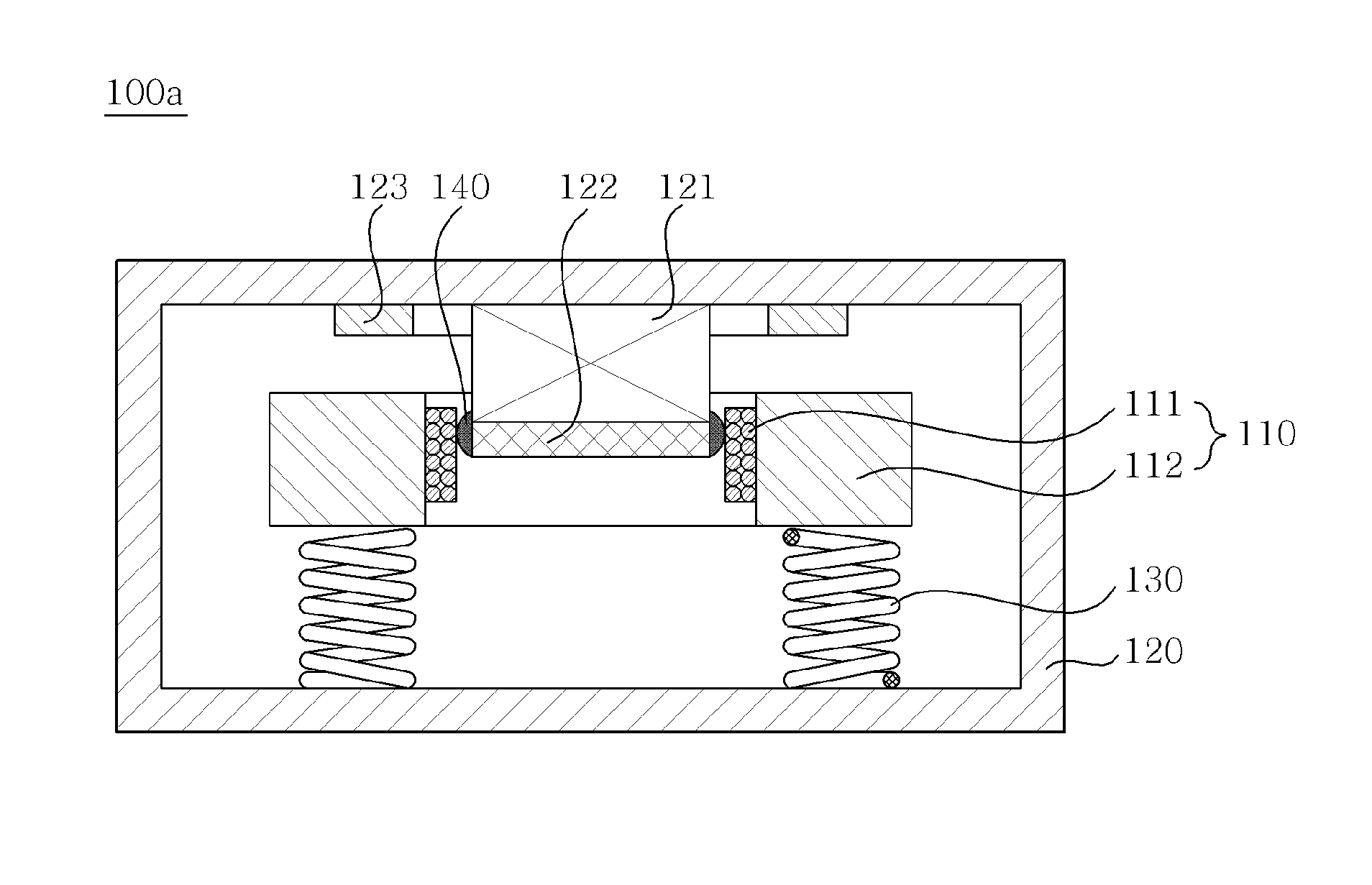
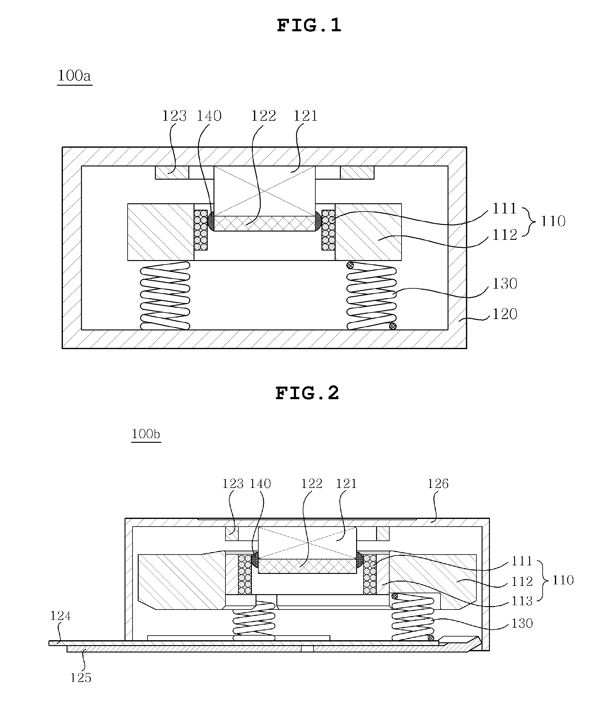
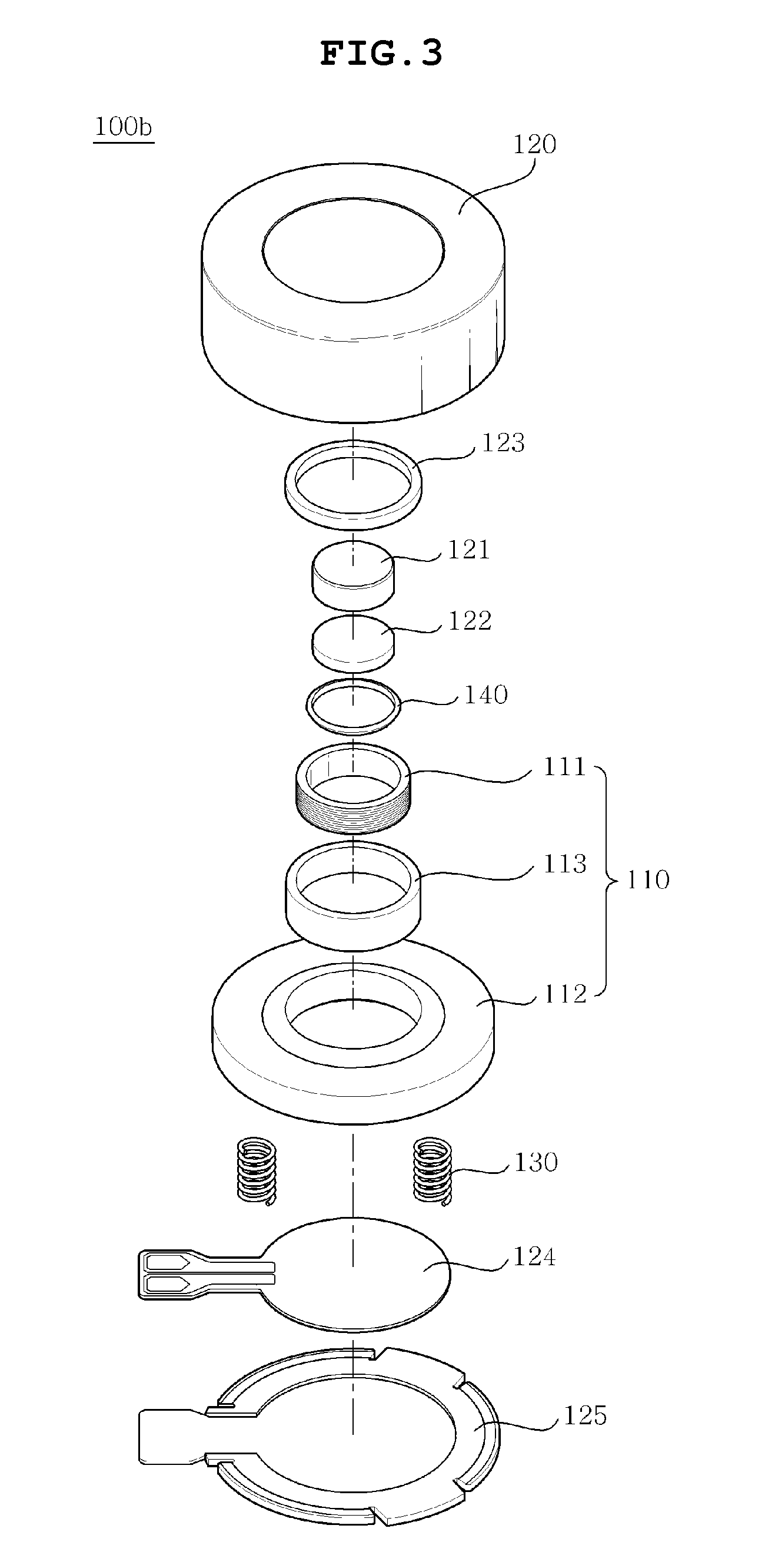
The present invention provides a linear vibrator with a damper and lubricating part that can stably vibrate and stop vibrating quickly. The damper prevents the vibratory unit from hitting the stationary unit when it moves linearly, while the lubricating part prevents noise and abrasion when the vibratory unit moves. The linear vibrator also reduces residual vibration of the spring by minimizing the period for which the vibratory unit stops vibrating.

Problems solved by technology

However, the vibration motor is problematic in that a brush passes through a gap between segments when the motor rotates, so that friction and sparks are generated, and thus the lifespan of the motor is reduced.
In addition to the problem, the vibration motor has other problems as well.
However, the conventional linear vibrator is problematic in that mechanical friction and abrasion and electric sparks are generated while the brush is passing through a gap between a segment of the commutator and another segment, so that impurities such as black powder are generated, and thus the lifespan of the linear vibrator is short.
Therefore, research into a linear vibrator which can generate more stable linear vibration and stop vibrating rapidly and stably is urgent.

Method used


Image

  • Linear vibrator
  • Linear vibrator
  • Linear vibrator

Examples


Embodiment Construction

[0026]The terms and words used in the present specification and claims should not be interpreted as being limited to typical meanings or dictionary definitions, but should be interpreted as having meanings and concepts relevant to the technical scope of the present invention based on the rule according to which an inventor can appropriately define the concept of the term to describe most appropriately the best method he or she knows for carrying out the invention.

[0027]The above and other objects, features and advantages of the present invention will be more clearly understood from the following detailed description taken in conjunction with the accompanying drawings. Herein, the same reference numerals are used throughout the different drawings to designate the same components. Further, when it is determined that the detailed description of the known art related to the present invention may obscure the gist of the present invention, the detailed description will be omitted.

[0028]He...


PUM


Abstract

Disclosed herein is a linear vibrator. The linear vibrator includes a stationary unit which has on an upper portion thereof a magnet generating a predetermined magnetic force and a yoke, and defines an internal space. A vibratory unit includes a coil mounted to face the magnet and applying an electric current, and a mass body. A spring is secured at a lower end thereof to the stationary unit and secured at an upper end thereof to the vibratory unit, thus elastically supporting the linear motion of the vibratory unit. A lubricating part is provided between an outer circumference of each of the magnet and the yoke and the coil, thus preventing noise and abrasion when the vibratory unit moves linearly, in addition to maintaining a vibration.

Description

CROSS REFERENCE TO RELATED APPLICATION[0001]This application claims the benefit of Korean Patent Application No. 10-2009-0119244, filed on Dec. 3, 2009, entitled “LINEAR VIBRATOR”, which is hereby incorporated by reference in its entirety into this application.BACKGROUND OF THE INVENTION[0002]1. Technical Field[0003]The present invention relates to a linear vibrator.[0004]2. Description of the Related Art[0005]The most important feature of an electronic device, such as a mobile phone, is the generation of vibration. A vibration motor is a means for generating vibration and is constructed so that its axis is eccentric or the center of gravity is non-uniformly distributed to one side and thereby the motor generates vibrations as it rotates.[0006]However, the vibration motor is problematic in that a brush passes through a gap between segments when the motor rotates, so that friction and sparks are generated, and thus the lifespan of the motor is reduced. In addition to the problem, the...

Claims


Application Information

Patent Timeline
Patent Type & Authority Patents(United States)
IPC IPC(8): H02K33/00
CPCH02K33/18H02K3/52H02K7/086
Inventor CHOI, JUN KUN
Owner MPLUS
Learn More