Radio link failure detection procedures in long term evolution uplink and downlink and apparatus therefor
a technology of radio link and failure detection procedure, applied in the field of wireless communication methods and apparatus, can solve the problems of inefficiency of dedicated channel support for srbs and traffic may not be continuous
- Summary
- Abstract
- Description
- Claims
- Application Information
AI Technical Summary
Problems solved by technology
Method used
Image
Examples
first embodiment
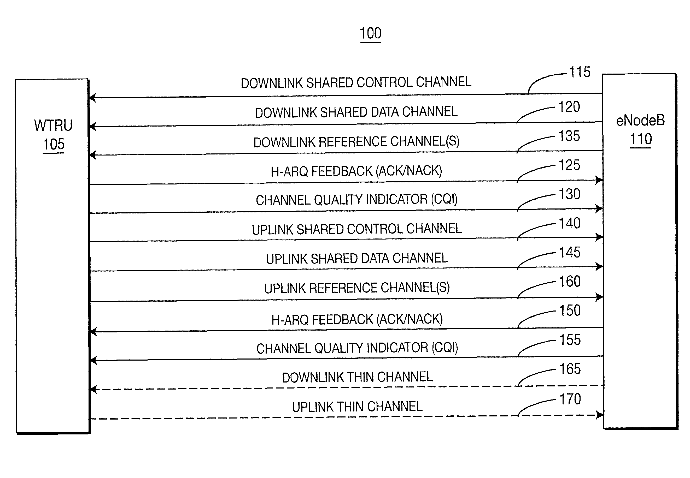
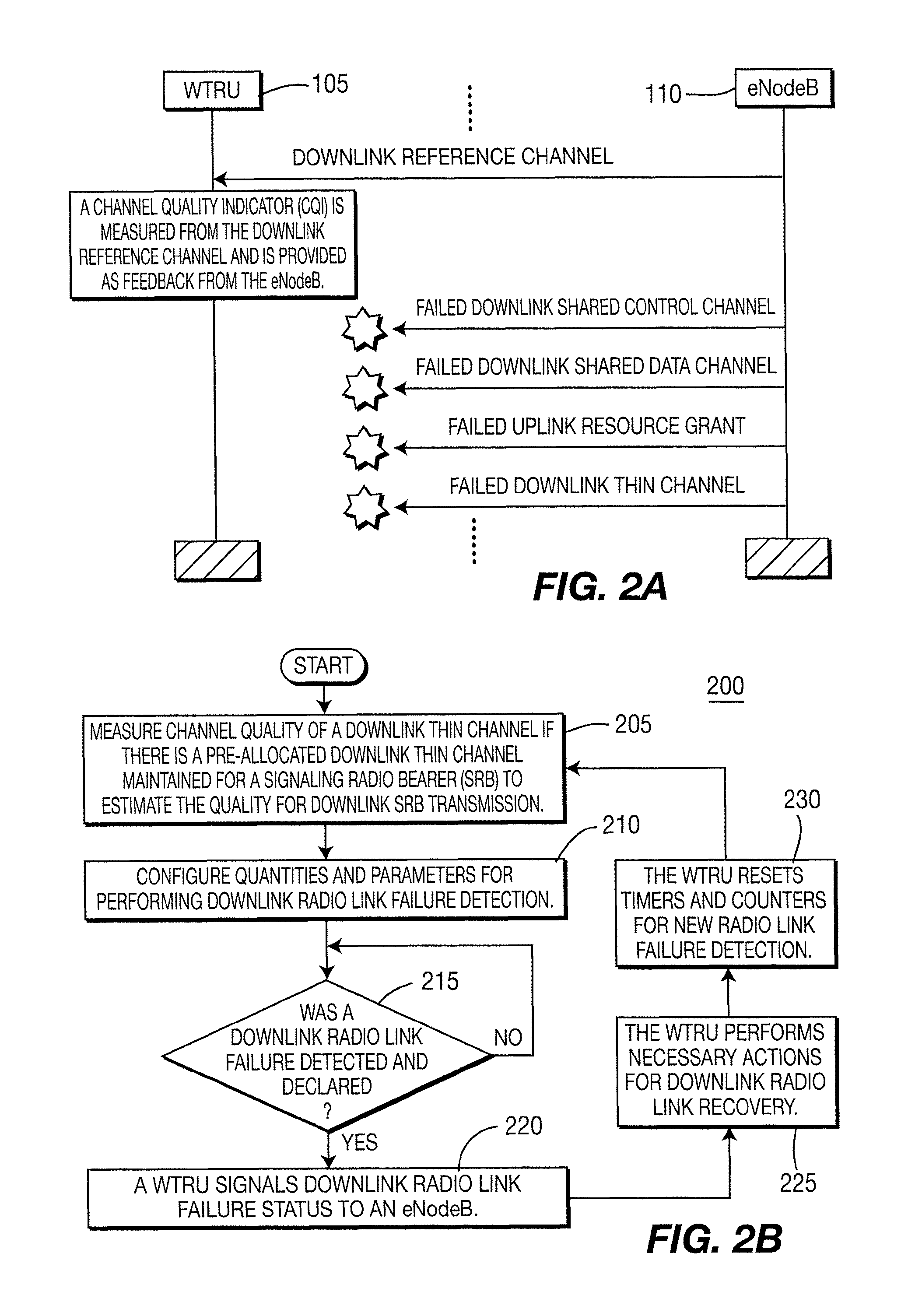
[0060]In accordance with the present invention, a high level DL RL detection procedure for a keep alive channel scenario of SRBs a pre-allocated DL thin channel is maintained. Where there is a pre-allocated DL thin channel maintained for SRB, the channel quality is measured on a DL thin channel is preferably selected as a main quantity to estimate the quality for DL SRB transmission. Other estimation quantities are selected to serve as a complimentary approach to assist the DL RL failure detection is selecting the combination of estimation quantities with which to configure the WTRU.
second embodiment
[0061]In accordance with the present invention, a high level DL RL detection procedure for a non-keep alive channel scenario of SRBs is implemented. In this case, there is no pre-allocated DL thin channel for SRB service. Although there are other periodic DL receptions, such as DL reference channels, that are not directly related to the DL SRB transmission. Accordingly, such other periodic DL receptions are preferably only used in combination with other quantities which preferably includes the shared data channel transmitting the DL SRBs.
[0062]FIG. 2B is a flow diagram of a method 200 for detecting DL RL failure. In step 205, the channel quality of a DL thin channel is measured if there is a pre-allocated DL thin channel maintained for an SRB to estimate the quality for DL SRB transmission. In step 210, quantities and parameters are configured for performing DL RL failure detection which is then conducted in step 215. If a DL RL failure is detected and declared in step 215, a WTRU s...
third embodiment
[0086]In accordance with the present invention, a keep alive channel scenario of SRBs is implemented as follows:
[0087]1) Since there is a pre-defined UL thin channel maintained for SRB in this scenario, it is proposed to measure the channel quality on UL thin channel as a main factor to estimate the quality for UL SRB transmission. The DL thin channel may be used to probe, (i.e., “ping”), for RL failure. It may probe based on criteria similar to those used to determine UL RL failure.
[0088]2) Other estimation quantities can be used as a complimentary approach to assist the UL RL failure detection. Exact quantities and parameters should be configured before the start of the detection procedure.
[0089]3) If the configured estimation quantities are not meeting certain thresholds within a pre-configured time period, then UL RL failure is detected and it should be declared, then:[0090]a) The eNodeB should signal the failure status to WTRU;[0091]b) The eNodeB should take the necessary actio...
PUM
 Abstract
Description
Claims
Application Information
 - R&D
- Intellectual Property
- Life Sciences
- Materials
- Tech Scout
- Unparalleled Data Quality
- Higher Quality Content
- 60% Fewer Hallucinations
Browse by: Latest US Patents, China's latest patents, Technical Efficacy Thesaurus, Application Domain, Technology Topic, Popular Technical Reports.
© 2025 PatSnap. All rights reserved.Legal|Privacy policy|Modern Slavery Act Transparency Statement|Sitemap|About US| Contact US: help@patsnap.com


