
Ergonomic surgeon control console in robotic surgical systems

a robotic surgery and control console technology, applied in the field of physical ergonomics and ergonomic equipment, can solve the problems increasing the likelihood of tissue damage caused by repetitive mis-application of energy, and difficulty in seeing the effect of inadvertent application of energy to the tissu

Active Publication Date: 2012-02-21
INTUITIVE SURGICAL +1
View PDF13 Cites 1272 Cited by
  • Summary
  • Abstract
  • Description
  • Claims
  • Application Information

AI Technical Summary

Benefits of technology

The solution enhances surgical precision and efficiency by reducing the risk of tissue damage and improving control over multiple instruments, allowing surgeons to focus on the procedure without diverting attention from the surgical site.

Problems solved by technology

When viewing an image of an electrosurgical tool and tissue on a display device captured through a camera, it may be difficult to see the effect of an inadvertent application of energy to the tissue.
While a single mis-application of energy to tissue may cause some damage, increasing damage is likely to be caused to tissue with repetitive mis-application of energy.
The inadvertent application of energy to tissue may be caused by a mis-positioned foot over an incorrect pedal.
The inadvertent application of energy to tissue may also be caused surgeon confusion as to which of a plurality of electrosurgical tools in the surgical site is being energized.
Moreover, if a surgeon's concentration is narrowly focused on the wrong surgical tool, he may not see the tissue damage being done by its mis-application.
Furthermore with additional types of robotic surgical tools being used with controllable equipment, it has become more difficult for a surgeon to simultaneously control all of the desired instruments.

Method used


Image

  • Ergonomic surgeon control console in robotic surgical systems
  • Ergonomic surgeon control console in robotic surgical systems
  • Ergonomic surgeon control console in robotic surgical systems

Examples


Embodiment Construction

[0036]In the following detailed description of the embodiments of the invention, numerous specific details are set forth in order to provide a thorough understanding of the embodiments of the invention. However, it will be obvious to one skilled in the art that the embodiments of the invention may be practiced without these specific details. In other instances well known methods, procedures, components, and circuits have not been described in detail so as not to unnecessarily obscure aspects of the embodiments of the invention.

Introduction

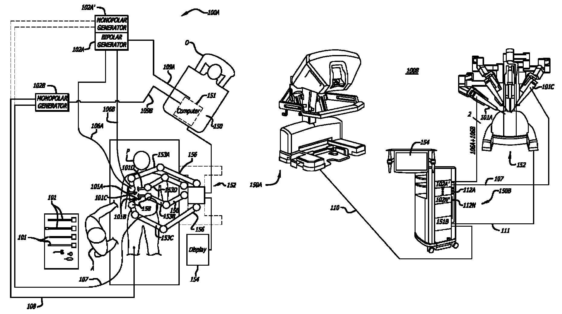
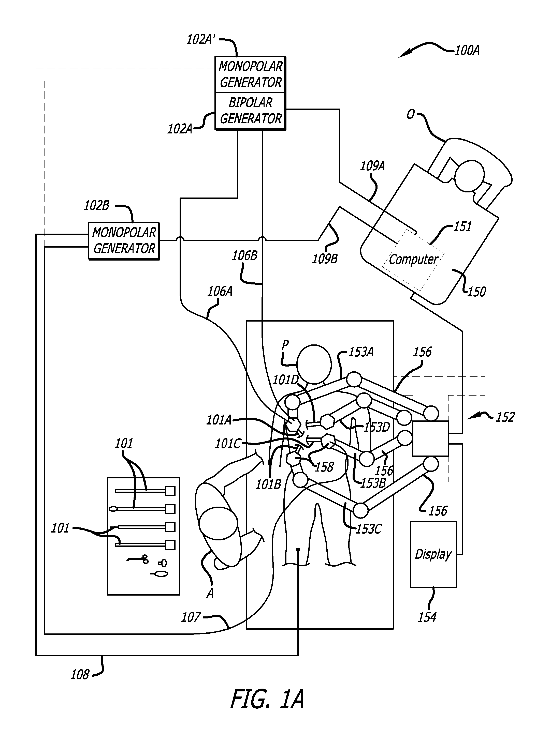
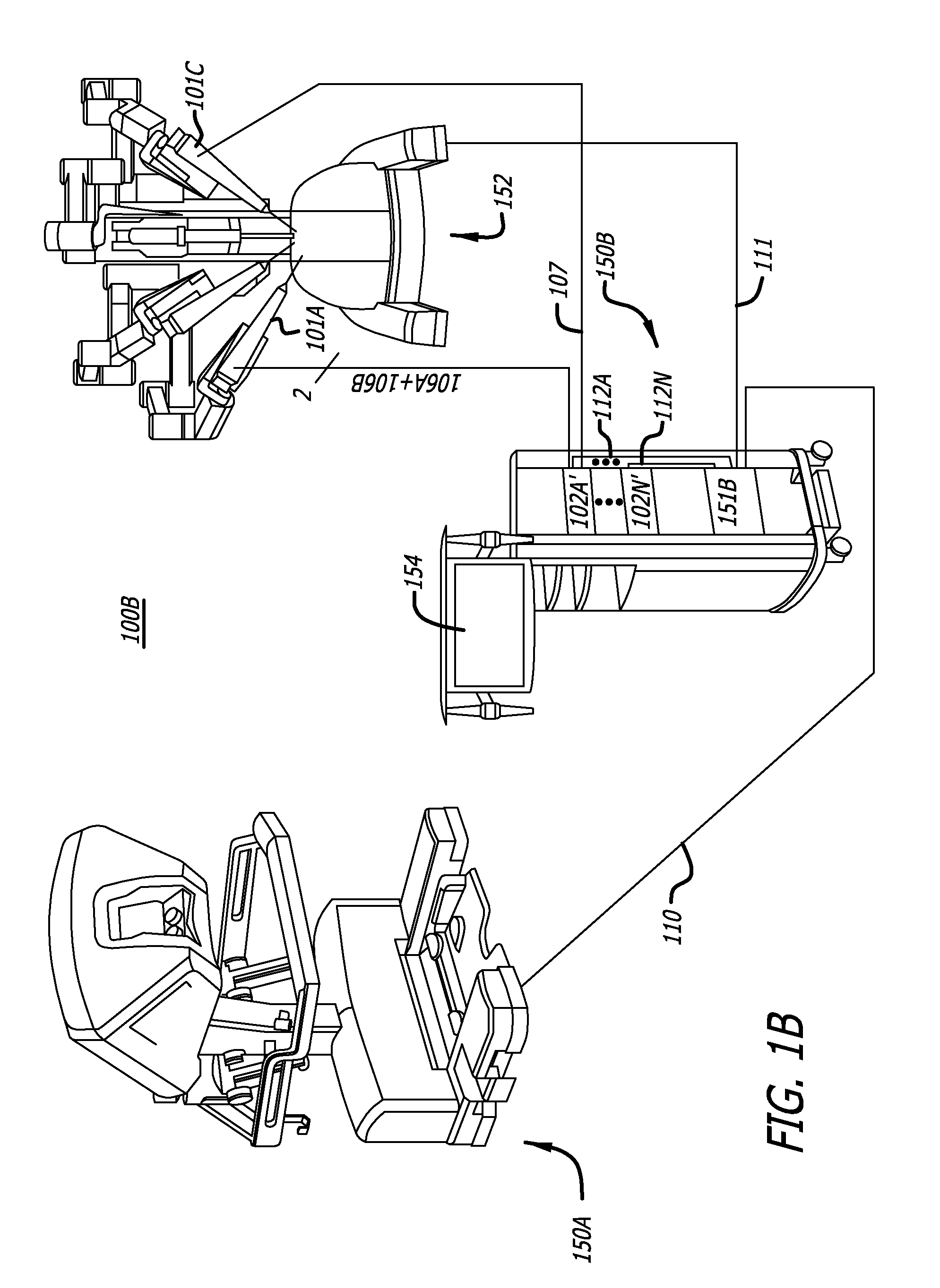
[0037]Robotic surgery may be used to perform a wide variety of surgical procedures, including but not limited to open surgery, neurosurgical procedures (such as stereotaxy), endoscopic procedures (such as laparoscopy, arthroscopy, thoracoscopy), and the like. During these robotic surgical procedures, surgeons may use high voltage, low current electrical energy of various wave forms to perform such tasks as cautery, cutting tissue, or sealing a vess...


PUM


Abstract

A control console to remotely control medical equipment is disclosed having a base with an ergonomically adjustable pedal system. The base further has an opening to receive the pedal system. The pedal system includes a moveable pedal tray with a pedal base. The tray includes a first left pedal assembly and a first right pedal assembly, and an upper tier having a second left pedal assembly and a second right pedal assembly respectively in alignment with and elevated above the first left pedal assembly and the first right pedal assembly. Rollers are rotatable coupled to the moveable pedal tray to allow it roll over a floor. A drive assembly is coupled between the moveable pedal tray and the base. The drive assembly applies a force to the to roll the moveable pedal tray over the floor within the opening of the base.

Description

FIELD[0001]The embodiments of the invention are generally related to physical ergonomics and ergonomic equipment.BACKGROUND[0002]Robotic surgical systems may have multiple robotic arms to which a plurality of robotic surgical tools (also referred to as robotic surgical instruments) may be coupled. One such category of robotic surgical tools is electrosurgical tools which includes a monopolar electrosurgical tool or a bipolar electrosurgical tool as well as harmonic, laser, ultrasound tools. Another category of robotic surgical tools is tissue manipulation tools which may have articulated end effectors (such as jaws, scissors, graspers, needle holders, micro dissectors, staple appliers, tackers, suction / irrigation tools, clip appliers, or the like) or non-articulated end effectors (such as cutting blades, irrigators, catheters, suction orifices, or the like) without electrosurgical elements. While electrosurgical tools are mechanically coupled to a robotic arm to control its movement...

Claims


Application Information

Patent Timeline
Patent Type & Authority Patents(United States)
IPC IPC(8): B64C13/20
CPCA61B19/2203Y10T74/20A61B19/56A61B2019/2223A61B2017/00477A61B19/5212A61B2017/00973A61B34/25A61B90/361A61B34/30A61B34/37G16H20/40G16H40/67
Inventor GOLDBERG, RANDAL P.HANUSCHIK, MICHAELHAZEBROUCK, HENRYMILLMAN, PAULKAPOOR, DEEPAKZABINSKI, JOHNROBINSON, DAVIDWEIR, DAVIDBROGNA, SALVATORE J.
Owner INTUITIVE SURGICAL
Learn More