Optical-based cell deformability

a technology of optical cells and deformation, applied in the field of optical cell deformation, can solve the problems of significant adverse health effects, limited shelf life of conjugates, and reagents added to the cost of tests, and achieve the effect of increasing the availability of practical bioassay platforms and lowering costs

Active Publication Date: 2012-02-21
COLORADO SCHOOL OF MINES
View PDF124 Cites 6 Cited by
  • Summary
  • Abstract
  • Description
  • Claims
  • Application Information

AI Technical Summary

Benefits of technology

[0005]It would be remarkably useful to implement a general, reagentless method akin to morphological examination that could be used as a “first-pass” means of identifying the cell types in a sample and determining use of specific reagents. Such devices would not require careful storage (e.g. refrigeration) or the disposal of potentially toxic reagents. These issues are all critical for lowering the cost and increasing the availability of practical bioassaying platforms for both laboratory and portable, point-of-care applications.
[0012]The flexibility of eukaryotic cells depends primarily on the cytoskeleton, which is comprised of actin filaments, microtubules, and intermediate filaments. The related cellular mechanical properties are a marker of cell health, and mechanical dysfunctions lead to significant adverse health effects. For example, the deformability of malignantly transformed cells is known to be larger than that of normal cells, and contributes to their motility, enabling them to migrate from the source and spread throughout the body (i.e. metastasize). In the context of hematology, cell rheology is a well-known factor in microcirculation. Erythrocytes and leukocytes must deform significantly to pass through the smallest blood vessels. Although the abnormal morphology of sickle cells is well known to cause impaired circulation, their decreased deformability is also a cause of impaired microcirculation. This approach to determining cell type and function could lead to cheaper and useful lab and clinical bioanalysis.
[0022]The re-orientation of particles in a high-throughput system helps to increase the accuracy of particle counting as well as standardize the orientation of particles prior to deformation and measurement. In accordance with at least one embodiment of the present invention, the same source of light that is used to re-orient the cell or similar object may also be used to deform the cell or similar object. This may be accomplished by applying a first optical force with the optical source that is sufficient to re-orient the cell or similar object and then applying a second larger optical force with the same optical source that is sufficient to deform the cell or similar object. The application of the first optical force may be applied upstream in the microfluidic channel as compared to the point where the second optical force is applied to the cell or similar object.
[0023]It is yet another aspect of the present invention to provide a mechanism for executing colloidal synthesis and / or tissue engineering. In accordance with at least one embodiment of the present invention cell alignment and / or deformation may be facilitated by application of optical forces to the cell. While the cell has a preferred alignment and / or deformation, the cell may be cured with the application of a curing means (e.g., the application of UV light to the cell may be a means of curing the cell) thereby preserving the preferred alignment and / or deformation of the cell. Colloidal synthesis and / or tissue engineering via a deformation and curing method may be useful to mark certain cells. For example, once a cell has been cured in a preferred alignment and / or deformation that particular cell can be uniquely identified among a plurality of otherwise similar cells that do not have the same alignment and / or deformation. In this sense, providing the ability to cure a cell in a preferred alignment and / or deformation may allow a relatively non-invasive way of tagging cells for later analysis.
[0024]In a more particular tissue engineering application, a collection of cells may be scanned with a light source that provides an optical force sufficient to create a preferred orientation (i.e., preferred cell alignment and / or deformation) in each cell in the collection of cells. Once a preferred orientation is achieved, the cells may be cured (e.g., via application of light having a predetermined wavelength to the cells) thereby causing the collection of cells to all have the preferred orientation. By fixing a collection of cells in a preferred orientation it may be easier to grow / add additional cells along the same preferred orientation without continually orienting and curing the added cells. Additionally, a collection of cells that are configured in a preferred orientation may exhibit certain advantageous qualities, such as a stronger cell structure as compared to a collection of cells that do not have the same preferred orientation.

Problems solved by technology

However, fluorescence detection requires labeling, typically with fluorophore-antibody conjugates, which brings a number of disadvantages: (i) these conjugates have shelf-life limitations and storage requirements, (ii) the reagent adds to the cost of the test, which scales with the number of cell types to be identified (i.e. number of reagents in the device), (iii) most importantly, a specific reagent must be developed for each different cell type, therefore one must decide in advance which cell types are to be detected.
The related cellular mechanical properties are a marker of cell health, and mechanical dysfunctions lead to significant adverse health effects.
Although the abnormal morphology of sickle cells is well known to cause impaired circulation, their decreased deformability is also a cause of impaired microcirculation.

Method used


Image

  • Optical-based cell deformability
  • Optical-based cell deformability
  • Optical-based cell deformability

Examples


Embodiment Construction

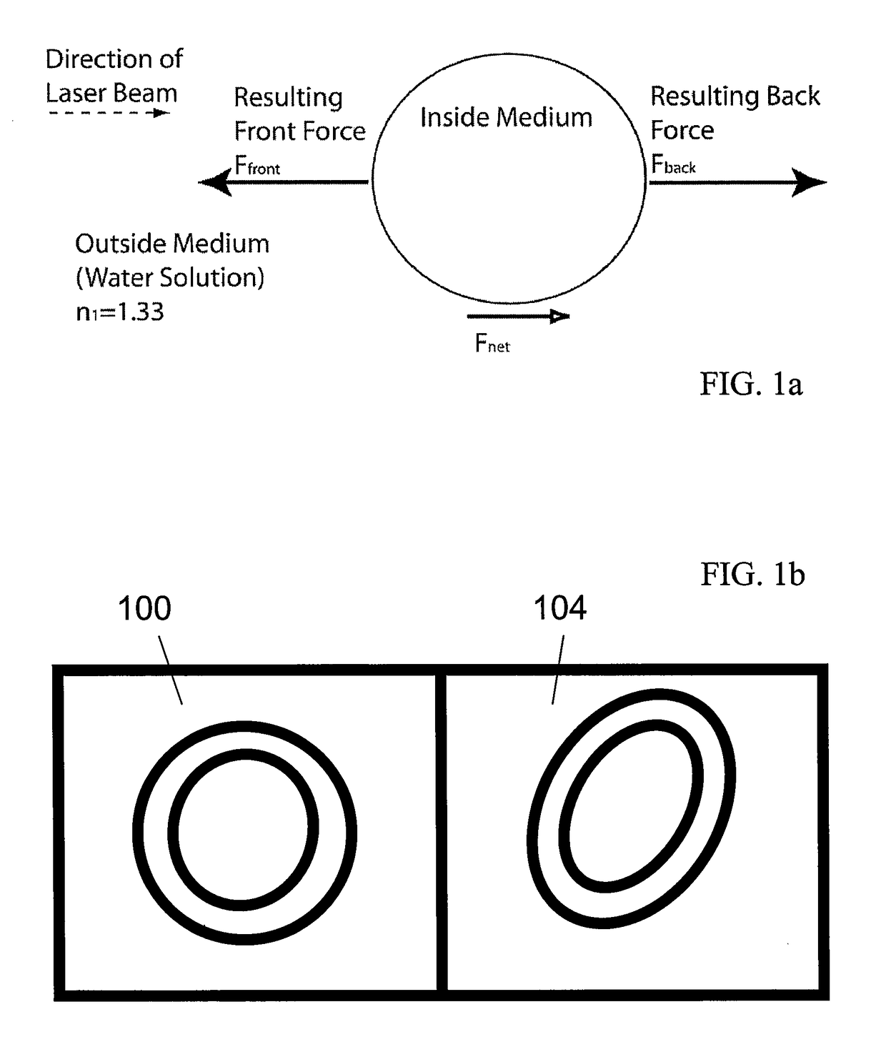
[0037]With reference now to FIG. 1a, details of orientation / deformation forces that can be exerted on a particle by a light source will be described in accordance with at least some embodiments of the present invention. Cells stretch in an optical system due to the same forces that cause them to be trapped in a laser beam. Not only does a laser exert a force to pull the particle into the Gaussian distribution of the laser, but it also exerts a small force in the negative z direction (downwards), pushing the particle away from the focal point.

[0038]This momentum transfer at the surface of some types of deformable particles causes the stretching force used to orient and / or deform cells. FIG. 1a specifically diagrams the forces acting on a particle when exposed to a single laser beam. When a particle is exposed to two opposing laser beams, the Fnet is cancelled out, and in systems that have deformable membranes, there is a deforming force that acts on the particle. It is possible to us...


PUM


Abstract

A system, method, and device for re-orienting and / or deforming cells and other objects is provided. The system, method, and device may include a high-throughput setup that facilitates the ability to orient, deform, analyze, measure, and / or tag objects at a substantially higher rate than was previously possible. A relatively large number of cells and other objects can be deformed, by optical forces for example, as the cells and other objects a flowed through the system.

Description

CROSS-REFERENCE TO RELATED APPLICATIONS[0001]This application claims the benefit of U.S. Provisional Application No. 60 / 947,899, filed Jul. 3, 2007, the entire disclosure of which is hereby incorporated herein by reference.[0002]The U.S. Government has a paid-up license in this invention and the right in limited circumstances to require the patent owner to license others on reasonable terms as provided for by the terms of DBI-0454686 awarded by the National Science Foundation.FIELD OF THE INVENTION[0003]The invention relates to laser configurations within microfluidic systems, among other systems, and optical-trapping based cell deformability measurements performed within dynamic, flowing systems.BACKGROUND OF THE INVENTION[0004]Many bioanalytical applications require cell sensing or detection. Fluorescence detection methods represent the most common choice; they are extremely widespread due to their sensitivity, selectivity, and ease of optical setup. However, fluorescence detectio...

Claims


Application Information

Patent Timeline
Patent Type & Authority Patents(United States)
IPC IPC(8): H01S1/00
CPCG21K1/006
Inventor SQUIER, JEFFMARR, DAVID W. M.APPLEGATE, ROBERTVESTAD, TORCHICHESTER, JUSTIN
Owner COLORADO SCHOOL OF MINES
Why Eureka
Try Eureka