
Variable air foil and spoiler

a technology of air foil and spoiler, which is applied in the direction of roofs, efficient propulsion technologies, transportation and packaging, etc., can solve the problems of affecting the maximum speed and performance of the vehicle, and other limitations of the related art, so as to increase the air speed, lift and drag of the air foil assembly, and achieve the effect of increasing airspeed

Inactive Publication Date: 2012-02-14
MOTOSKO III STEPHEN
View PDF22 Cites 9 Cited by
  • Summary
  • Abstract
  • Description
  • Claims
  • Application Information

AI Technical Summary

Benefits of technology

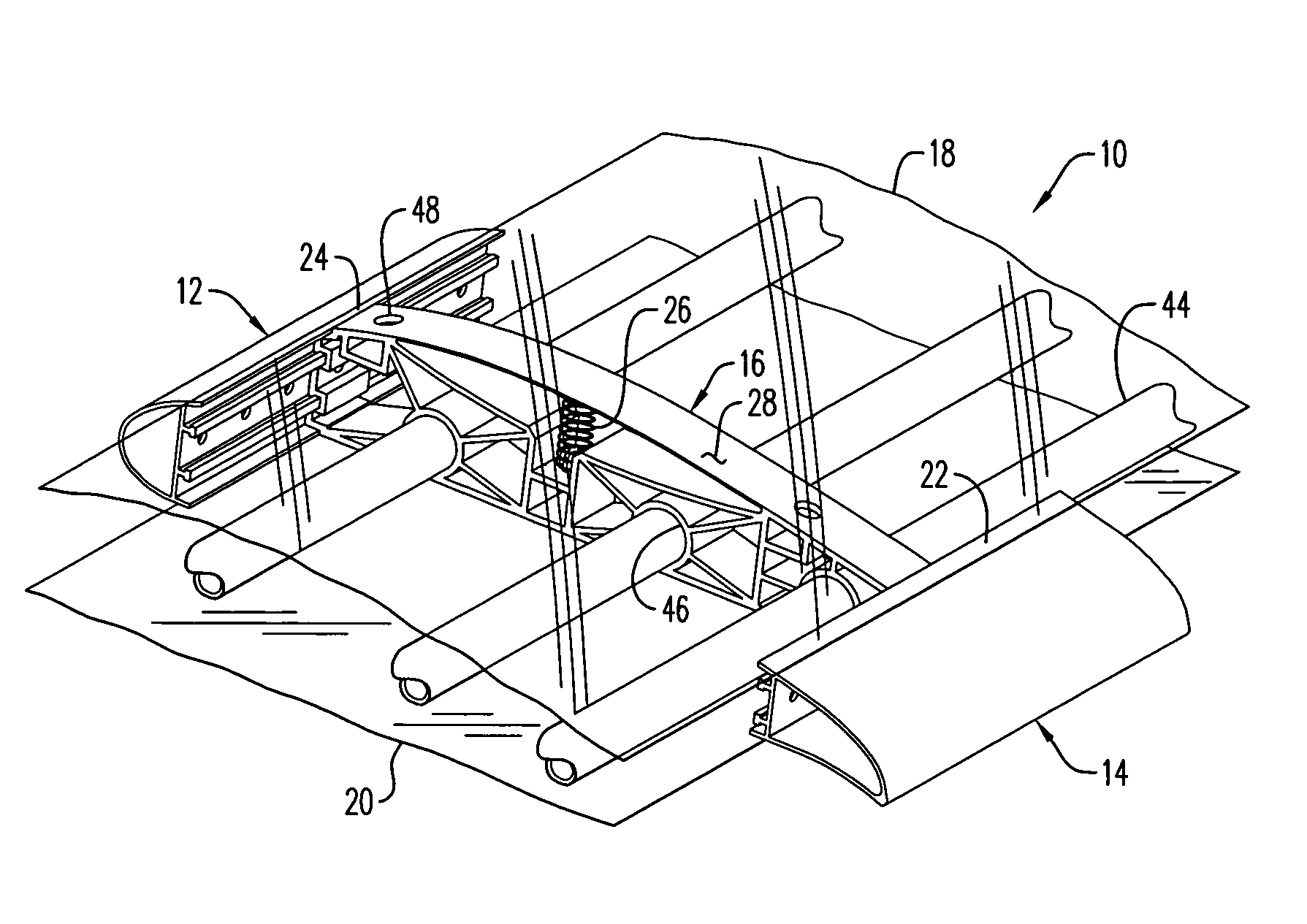
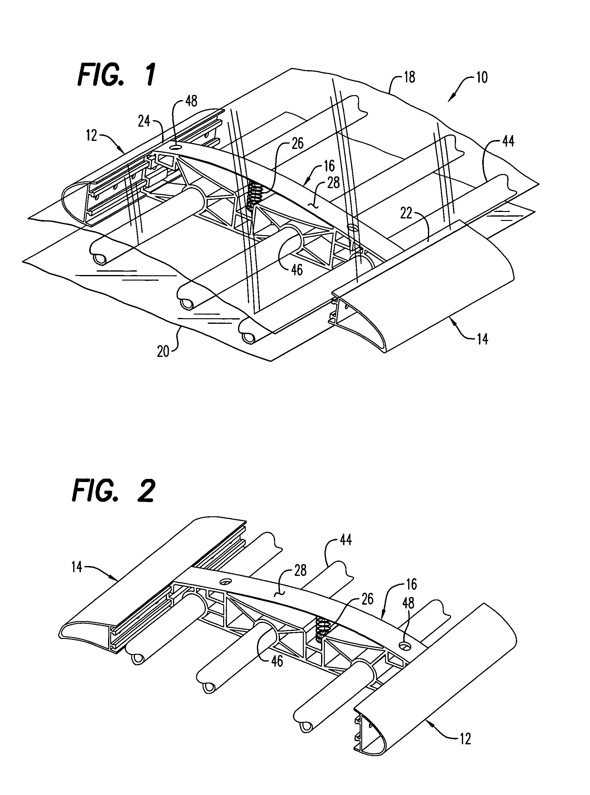
[0017]This invention is directed to a variable lift, variable drag, airfoil assembly including a leading edge and a trailing edge connected together in spaced apart relation and an elastic skin connected to and extending between the leading and trailing edges to define an airfoil profile. A resilient spring member positioned within the airfoil profile exerts biased outward pressure against a central portion of the lifting surface of the elastic skin to automatically create a varying thickness of the airfoil profile responsive to increased air speed over the airfoil profile wherein lift and drag of the airfoil assembly are proportionately reduced as airspeed increases. In another embodiment, the airfoil assembly is inverted in the form of a rear spoiler of a land vehicle oriented transversely across a rear portion of the vehicle to produce an increasing downward road gripping force on the rear wheels of the vehicle with increasing vehicle speed while reducing the drag produced by the airfoil assembly.
[0018]It is therefore an object of this invention to provide an airfoil which proportionately produces less lift when moved through air, the airfoil being automatically reduced in overall thickness in proportion to velocity through air.
[0019]Another object of this invention is to provide an automatically diminishing lift and drag of an airfoil as the airfoil is moved at greater velocities through air.
[0020]Yet another object of this invention is to provide a spoiler for the rear of a high speed vehicle which produces downward stabilizing force on the rear wheels of the vehicle and which downward force proportionately decreases the rate of increasing lift at higher speeds and correspondingly results in proportionately less drag to slow the vehicle.

Problems solved by technology

However, due to the conventional fixed configuration of the spoilers, they can become a bit of a detriment to achieving the vehicle maximum speed and performance due to the fact that the drag produced at higher vehicle speeds will inhibit achieving maximum racing performance of the vehicle.
Other limitations of the related art will become apparent to those skilled in the art upon a reading of the specification and a study of the drawings.

Method used


Image

  • Variable air foil and spoiler
  • Variable air foil and spoiler
  • Variable air foil and spoiler

Examples


Embodiment Construction

Lifting Airfoil

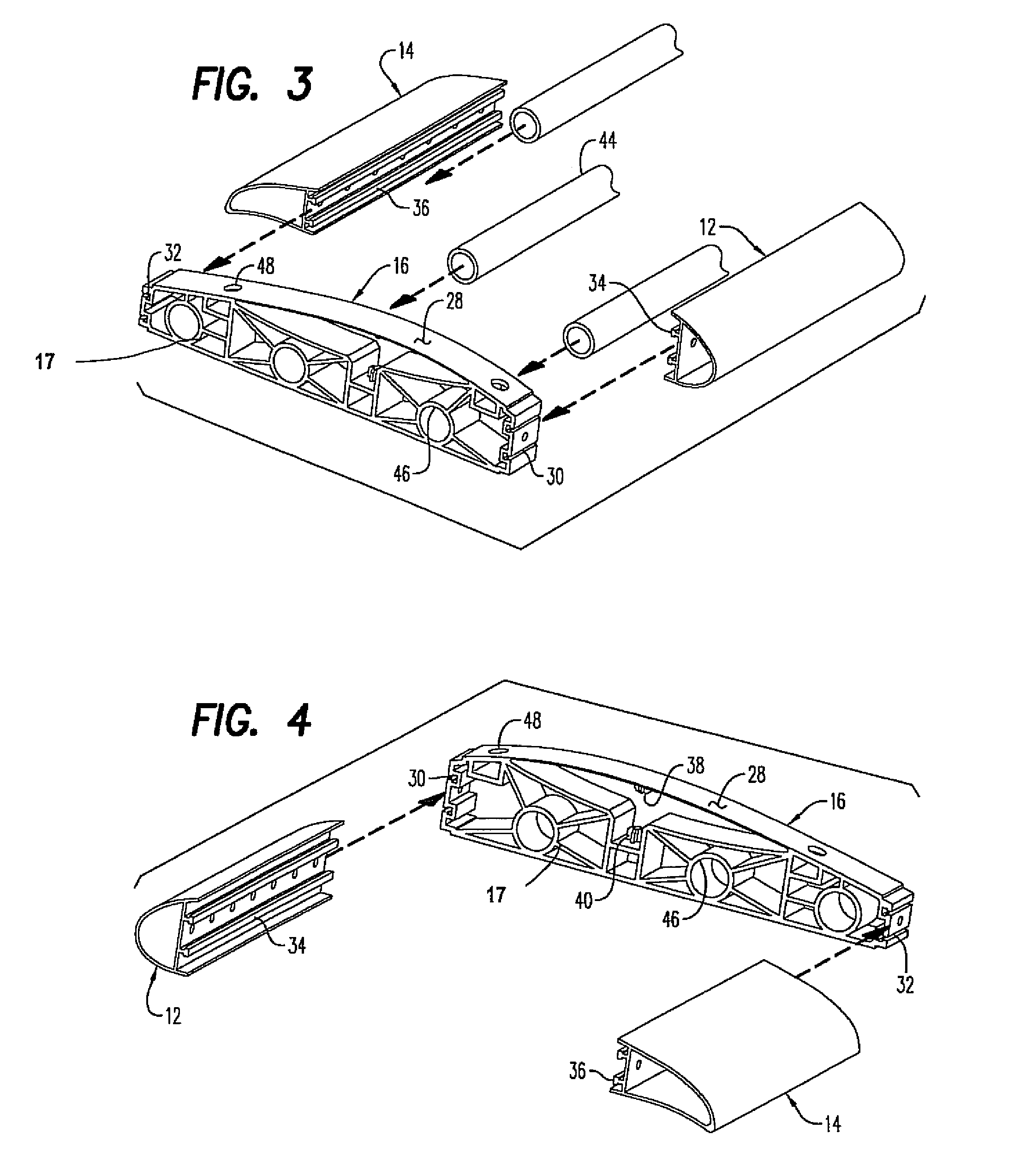
[0037]Referring now to the drawings, one embodiment of the invention shown in FIGS. 1 to 15 as an airfoil for producing lift such as for an aircraft, there shown generally at numeral 10 in FIGS. 1 and 5. The airfoil assembly 10 includes a leading edge member 12, a trailing edge member 14 spaced apart from the leading edge member 12, and at least one spaced transversely extending rib members 16 which are covered by a thin skin of transparent Mylar 18 and 20 which define the lifting and bottom airfoil surfaces, respectively.

[0038]Each of the rib members 16 includes C-shaped channels 30 and 32 along the leading and trailing faces thereof, respectively. As best seen in FIG. 4, channels 30 slidably interengage with elongated rails 34 lengthwise of the leading edge 12, while channels 32 slidably engage with rails 36 lengthwise of trailing edge 14. To strengthen the overall load carrying capability of this airfoil assembly 10, several spaced apart round spars 44 slidably may...


PUM


Abstract

A variable lift, variable drag airfoil assembly including a leading edge and a trailing edge connected together in spaced apart relation and an elastic skin connected to and extending between the leading and trailing edges to define an airfoil profile. A resilient spring member positioned within said airfoil profile exerts biased outward pressure against a central portion of the lifting surface of the elastic skin to automatically create a varying thickness of said airfoil profile responsive to increased air speed over the airfoil profile wherein lift and drag of the airfoil assembly are proportionately reduced as airspeed increases. In a preferred embodiment, the airfoil assembly is inverted in the form of a rear spoiler of a land vehicle oriented transversely across a rear portion of the vehicle to produce an increasing downward road gripping force on the rear wheels of the vehicle with increasing vehicle speed while reducing the drag produced by the airfoil assembly.

Description

CROSS-REFERENCE TO RELATED APPLICATIONS[0001]Not applicableSTATEMENT REGARDING FEDERALLY SPONSORED RESEARCH OR DEVELOPMENT[0002]Not applicableINCORPORATION-BY-REFERENCE OF MATERIAL SUBMITTED ON A COMPACT DISC[0003]Not applicableBACKGROUND OF THE INVENTION[0004]1. Field of the Invention[0005]This invention relates generally to lifting airfoil structures, and more particularly to an airfoil or vehicle spoiler which automatically varies the thickness of the airfoil and therefore proportionately alters the lifting and drag characteristics depending upon the velocity of the air passing over the airfoil.[0006]2. Description of Related Art[0007]Airfoil structures are typically used for creating lift such as in wing, tail and elevator surfaces of an aircraft. The most traditional of these airfoils are fixed, having a top or lifting surface which is longer by virtue of its arcuate configuration than that of the lower surface of the airfoil thus producing lift which enables an aircraft to bec...

Claims


Application Information

Patent Timeline
Patent Type & Authority Patents(United States)
IPC IPC(8): B64C3/44
CPCB64C3/48Y02T50/145Y02T50/10
Inventor MOTOSKO, III, STEPHEN
Owner MOTOSKO III STEPHEN
Learn More