
Teat cup liner

a lining and tea cup technology, applied in the field of liners, can solve the problems of teat tissue irritation, excessive pressure on teat tissue, undue stress, etc., and achieve the effect of uniform sealing, avoiding excessive pressure, and avoiding tissue irritation and vacuum loss

Active Publication Date: 2012-02-14
GEA FARM TECH
View PDF22 Cites 26 Cited by
  • Summary
  • Abstract
  • Description
  • Claims
  • Application Information

AI Technical Summary

Benefits of technology

[0010]The present invention overcomes the excessive pressure applied by a liner barrel with a circular cross-section and the tissue irritation and vacuum loss that can result from a liner barrel with a square cross-section. The present invention utilizes a liner barrel with a round cross-section in its upper portion and a square cross-section in its lower portion to obtain a uniform seal with minimal irritation in the upper portion of a teat and with reduced pressure applied to the lower portion of a teat.

Problems solved by technology

Since teats are essentially round in cross-section, the application of pressure from two sides can cause undue stress, irritation, and excessive pressure on teat tissue.
One downside to a square-barreled liner is that during the vacuum phase, the teat tissue tends to expand into the corners of the square barrel and cause irritation of teat tissue.
Barrel liners with square cross-sections tend not to form as secure a seal with teats, and premature release can occur.

Method used


Image

  • Teat cup liner
  • Teat cup liner
  • Teat cup liner

Examples


Embodiment Construction

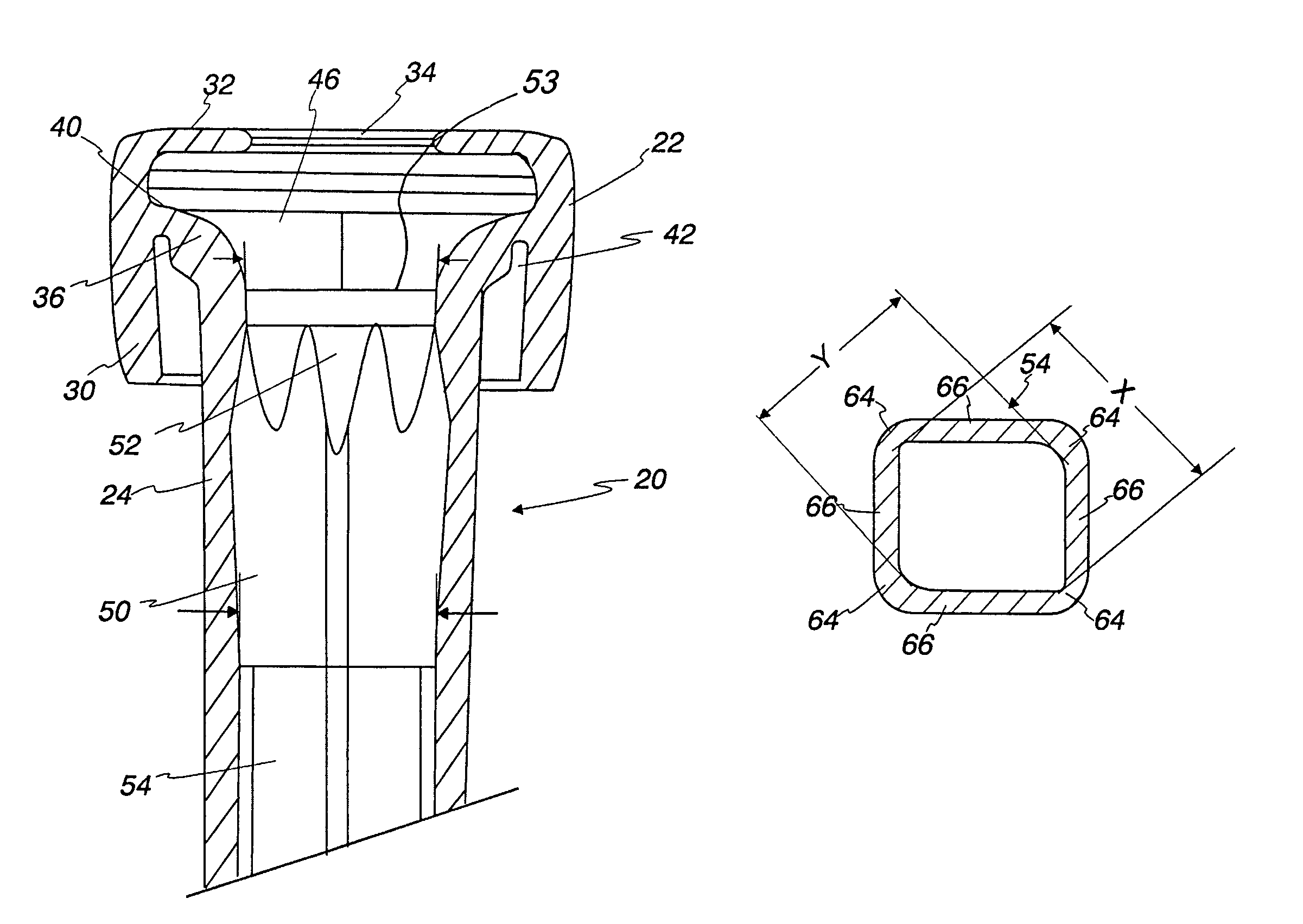
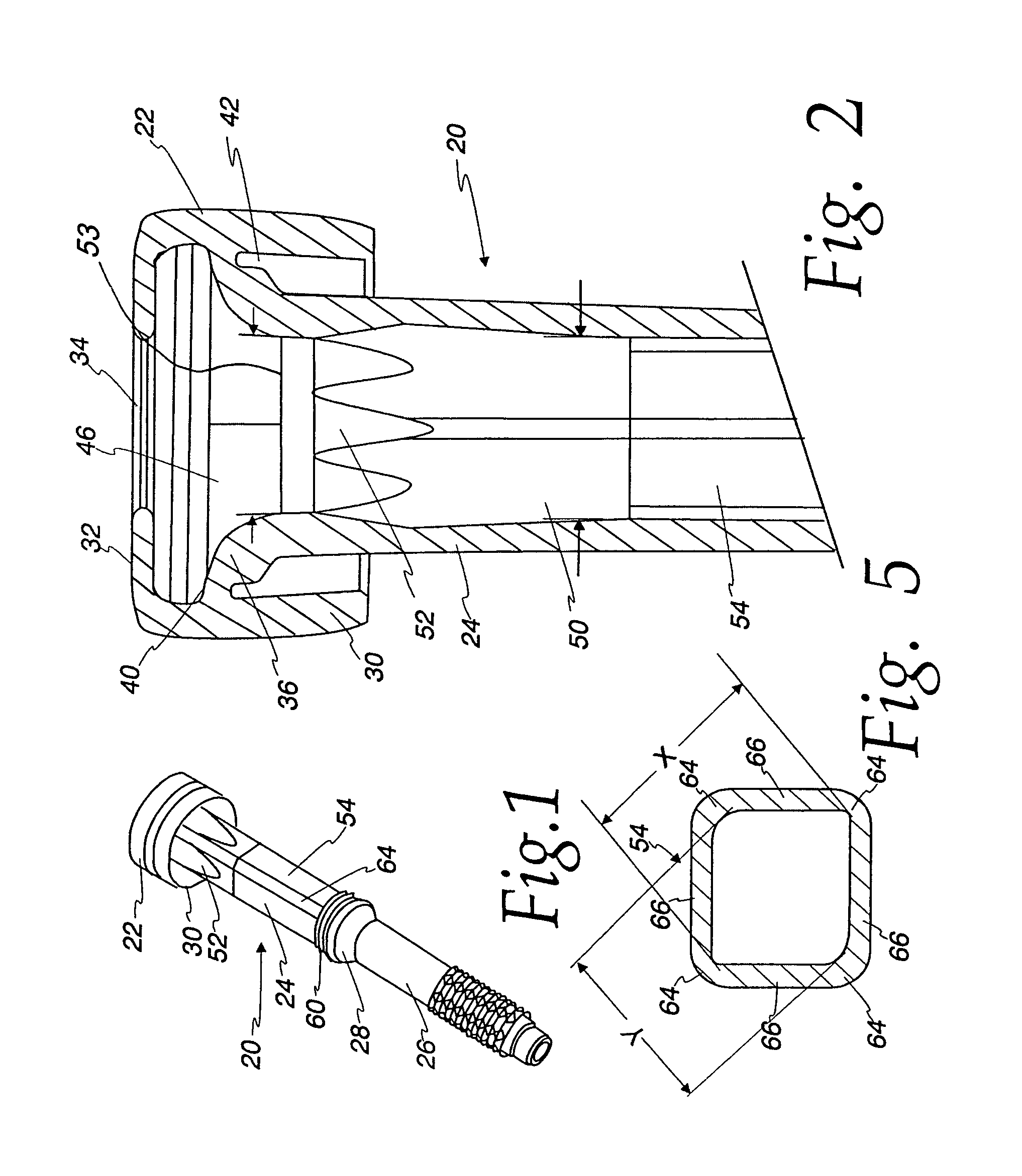
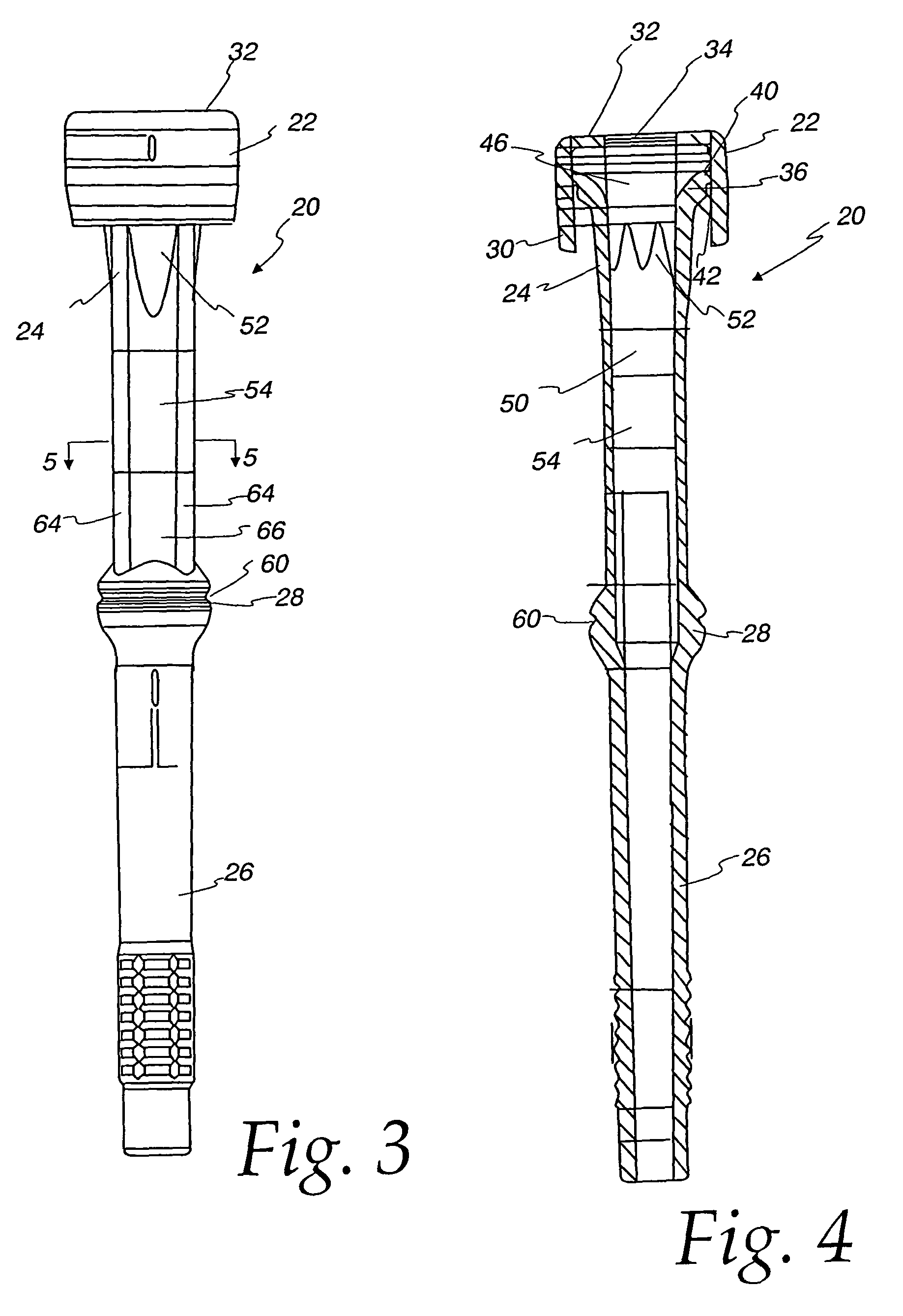
[0019]In the following detailed description of the preferred embodiments, the same reference numeral will be used to identify the same item in each of the drawings. Illustrated generally in FIGS. 1 through 4 is a teat cup liner 20 in accordance with the present invention, having an upper dome 22, a barrel 24, and an optional short milk tube 26. Typically, liners 20 are made of rubber or silicone and are molded in a single piece.

[0020]Liners 20 are shaped and sized to fit within a teat cup of a milking machine (not illustrated). The teat cup and liner 20 cooperate to form an inflation that alternates applying pressure and vacuum from a vacuum pump (not illustrated) to massage a dairy animal's teat to withdraw milk.

[0021]The liner 20 dome 22 includes an annular wall 30, an upper surface 32, a teat opening 34 in the upper surface 32, and a shoulder 36. The annular wall 30 is connected to an upper portion 40 of the shoulder 36, but is spaced apart from the rest of the shoulder 36 and th...


PUM


Abstract

A milking machine teat cup liner having a dome and a barrel, and the barrel has an upper transition portion and a lower square portion. The transition section mates with the round cross-section of the dome and the square cross-section of the lower square portion to provide superior vacuum seal with less irritation and damage to teat tissue.

Description

FIELD AND BACKGROUND OF THE INVENTION[0001]This invention relates generally to liners for milking machine teat cups, and more particularly to improved teat cup liners that provide a superior seal against a teat upper portion and a controlled collapse around a teat lower portion to reduce tissue irritation and damage while enhancing the milking process.[0002]Dairy animals, and particularly cows, are milked using automated milking machines. The milking machines include a milking unit including four teat cups, tubes downstream from the teat cups, a claw that acts as a manifold connected to the tubes for receiving milk, a pulsator, and pulsation tubes. The milking machines connect downstream with equipment for collecting milk.[0003]The interface between milking machine and animal is a flexible liner inside a teat cup. A teat fits inside the liner during milking. An annular space between the liner and the teat cup is called a pulsation chamber. Vacuum from a vacuum pump is controlled by ...

Claims


Application Information

Patent Timeline
Patent Type & Authority Patents(United States)
IPC IPC(8): A01J5/06
CPCA01J5/08
Inventor SELLNER, DUANE F.
Owner GEA FARM TECH
Learn More