Laser putting device

a laser putting and laser technology, applied in golf, sport equipment, golf accessories, etc., can solve the problems of user's inability to see the laser beam clearly, no right or wrong line up, etc., to improve the strike, improve the accuracy, and the effect of monolithic structur

Inactive Publication Date: 2012-02-07
KHANANAYEV VLADIMIR +1
View PDF9 Cites 6 Cited by
  • Summary
  • Abstract
  • Description
  • Claims
  • Application Information

AI Technical Summary

Benefits of technology

[0015]An advantage of the present invention is to provide the device which is sturdy, monolithic, and stable in keeping a factory calibrated device generating a laser beam, easily installed on the putter, using hard rests without the use of any tools, and does not need in a further adjustment of the laser beam direction.
[0016]Another advantage of the present invention is to provide the device is turning on by golfer's decision, being in a playing posture with unlimited place of a gripping a handle of the putter for checking only of a quality of aiming by the putter.
[0017]Still another advantage of the present invention is to provide the improved link for the suspension system that is stamped from a light weight sheet metal.
[0018]Still another advantage of the present invention is to provide a system designed to help the golfer to learn how to improve a strike and place the golf ball into a hole within short period of time and without necessity of using outdoor facility.
[0019]Still another advantage of the present invention is to provide the system that will allow the golfer to use the same independently without anyone's help wherein the golfer creates a visual memory of an aiming and muscular memory of a swing at a reflex level for just several hours of training.
[0020]Still another advantage of the present invention is to provide a putter wherein the location of the laser index unit relative the head portion is fixed and direction of the laser beam relative the striking surface is controlled.

Problems solved by technology

There is no right way or wrong way to line up and hit a golf ball.
Another drawback of these designs is that the user may not be able to see the laser beam clearly when looked at the ground because the laser beam extends from the front side of the striking face of the putter head.

Method used


Image

  • Laser putting device
  • Laser putting device
  • Laser putting device

Examples


Embodiment Construction

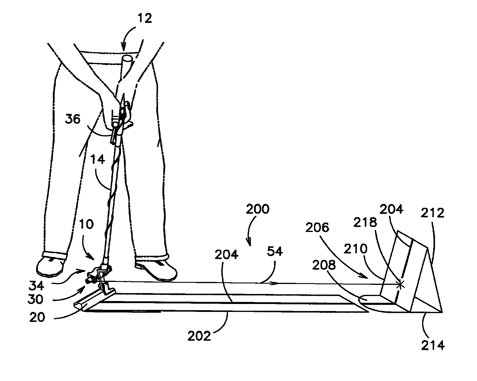
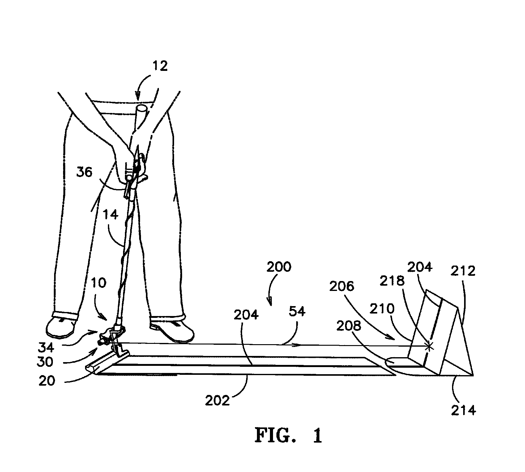
[0034]Referring to the Figures, wherein like numerals indicate like or corresponding parts, a laser putting device, generally shown at 10, (the device) of the present invention is used to assist a golfer (shown in phantom in FIG. 1) or those who begin training of in a golf. The device 10 is intended for training, and more particularly to improve aiming, swing, and impacts on a golf ball thereby landing the golf ball in a hole defined in golf green from any distances. The device 10 is connected to a standard putter, generally shown at 12 in FIGS. 1 and 2. The putter 12 includes a handle 16, an electrically conductive shaft 14, and a head portion 18 with a striking surface 20.

[0035]A neck 22 extends from the head portion 18 to interconnect the head portion 18 with the shaft 14. The neck 22 presents a rectangular configuration. A collar 24 is connected to the neck 22 to receive the shaft 14. The device 10 includes several parts connected to one another. These four main components of th...


PUM


Abstract

A laser putting device for a golf putter includes a guiding unit for generating a laser beam, a frame for supporting the guiding unit disposed in the frame, an activator connected to the golf putter and communicated with the guiding unit for turning the guiding unit between on and off positions thereby generating the laser beam. A bracket of the laser guiding device is adaptable to receive a tubular member of the guiding unit that has a mirror and a diode emitting the laser beam and guiding the laser beam into the mirror angled in the fashion to form the laser beam having 90 degrees thereby allowing the golfer to point the laser beam at the target point, such as a hole in a golf green. The laser guiding device help the golfer to learn how to improve a strike and place the golf ball into a hole within short period of time and without necessity of using outdoor facility.

Description

FIELD OF THE INVENTION[0001]The present invention relates to a laser putting device and more particularly to a golf putter with laser sighting and guiding device.BACKGROUND OF THE INVENTION[0002]Golf is one of the commonly played games around the world. Lots of people play the golf but only limited number of people really know how to play it right thereby striking the ball correctly in order to place the ball in the hole defined in the golf green. Those who struggle with game know how hard it is to get the ball aimed in the right direction and actually hit the ball in the same direction. Everyone has a unique stroke or technique for lining the ball up with the hole, swinging and actually striking the ball. There is no right way or wrong way to line up and hit a golf ball. There are different ways of training on how to master a perfect swing. There are numerous books and magazines that everyone can afford to either purchase or rent. Most golf courses worldwide offer lessons on golf, ...

Claims


Application Information

Patent Timeline
Patent Type & Authority Patents(United States)
IPC IPC(8): A63B69/36
CPCA63B69/3614A63B69/3685A63B69/3676A63B2071/0694A63B2210/50A63B2225/12
Inventor KHANANAYEV, VLADIMIRBOROCHIN, MARINA
Owner KHANANAYEV VLADIMIR
Why Eureka
Try Eureka