
Air conveyor with a device for orienting bottles vertically

a vertical orientation and air conveyor technology, applied in the direction of conveyor parts, bulk conveyors, loading/unloading, etc., can solve the problems of increasing aerodynamic drag and other problems, and achieve the effect of not decreasing the speed of bottles

Active Publication Date: 2012-02-07
KRONES AG
View PDF19 Cites 1 Cited by
  • Summary
  • Abstract
  • Description
  • Claims
  • Application Information

AI Technical Summary

Benefits of technology

[0006]Therefore, the object underlying the present disclosure is to render the bottle transfer to another conveyor in the end area of an air conveyor essentially less susceptible to failures without slowing down the bottles in the process.
[0010]To apply air to the bottle bodies, guide plates are typically used which are provided with gills or nozzles. Gills are slits worked into a guide plate through which air flows out in a preferred direction. Guide plates with nozzles are more complicated to manufacture, but permit a very precise airflow. Embodiments with combinations of gills and nozzles are also conceivable. The gills or nozzles can be located at different levels at the guide plates. For example, the gills or nozzles can be arranged in diagonal rows on the guide plates, preferred angles to the longitudinal sides of the guide plates being in a range of 20° to 40°. The arrangement of the gills or nozzles at different levels or the diagonal arrangement of the gills or nozzles permits to transport and vertically orient bottles of different sizes and different oblique positions in one and the same air conveyor. In case of bottles with a lower or higher own weight, the blowing strength can be correspondingly decreased or increased.

Problems solved by technology

However, as speed is increasing, aerodynamic drag also plays an increasing role.
However, when a bottle is to be transferred to another transport device (e.g. a sawtooth or zigzag star) at the end of an air conveyor, the oblique position of the bottles can cause difficulties.

Method used


Image

  • Air conveyor with a device for orienting bottles vertically
  • Air conveyor with a device for orienting bottles vertically
  • Air conveyor with a device for orienting bottles vertically

Examples


Embodiment Construction

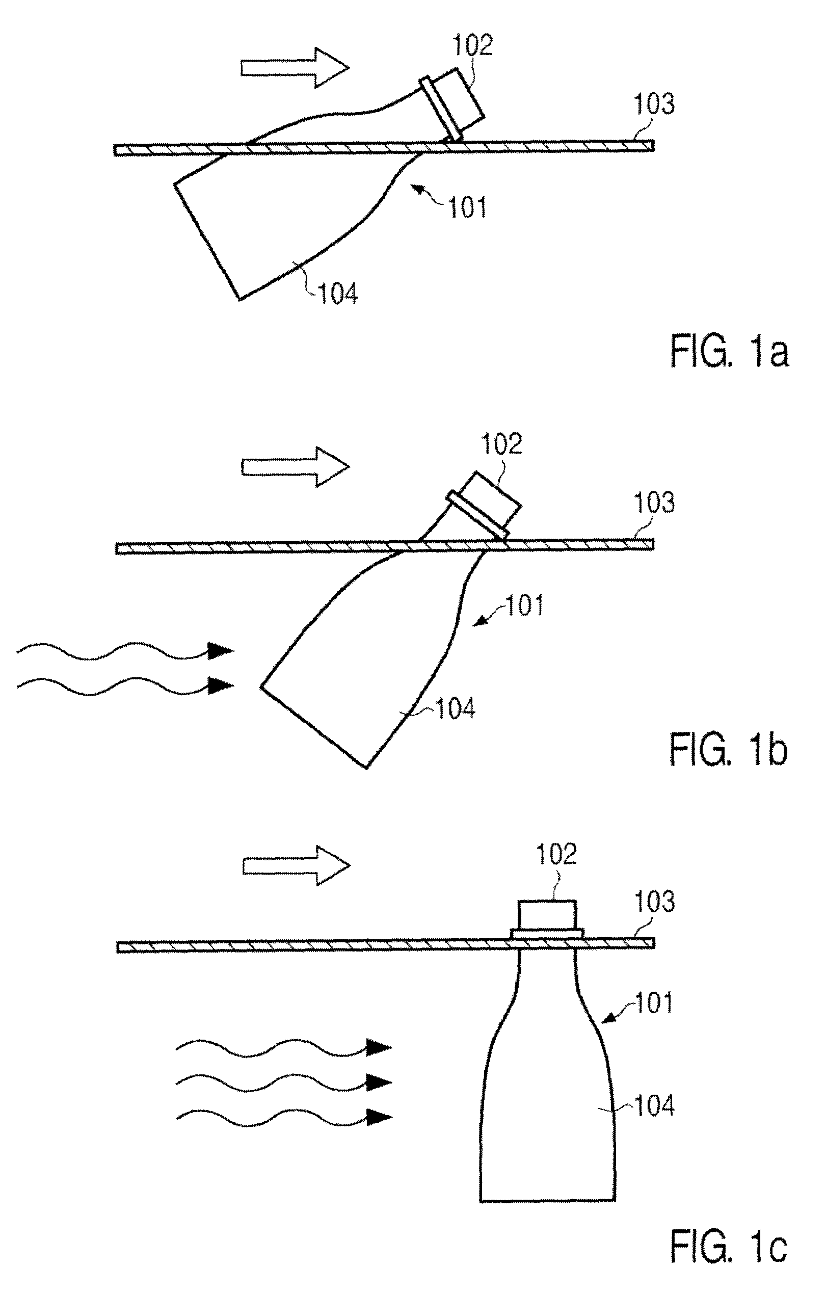
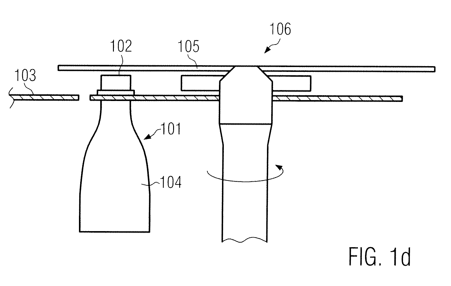
[0027]FIG. 1 illustrates the vertical orientation of a bottle 101 in an air conveyor. The air conveyor comprises, among others, two guide rails 103 situated at the same level at opposite sides, in FIG. 1 only one of them being shown. The guide rails 103 are arranged in pairs in parallel to each other. The distance between two guide rails 103 is selected such that the neck of a bottle just fits between the two guide rails 103 and the bottle 101 rests with the supporting ring of the bottle on the two guide rails 103. In the indicated air conveyor, air is applied to the bottle opening 102, so that the bottle 101 slides on the guide rails 103. The total direction of movement of the bottle 101 is indicated by an arrow. In FIG. 1a, the bottle 101 is in an extreme oblique position as only in the area of the bottle opening 102, air is applied to the bottle 101, and as the aerodynamic drag caused by the progressive movement mainly acts on the bottle body.

[0028]In FIG. 1b, air is additionally...


PUM


Abstract

An air conveyor for transporting plastic bottles, in which bottles are driven by applying air, in the area of the bottle openings. In a partial area of the air conveyor, means are provided to apply air to the bottle bodies. These means are arranged such that the bottles are essentially oriented vertically with the openings of the bottles facing upwards and the bottom of the bottles facing downwards.

Description

CROSS-REFERENCE TO RELATED APPLICATION[0001]The present application claims the benefit of priority of German Patent Application No. 102007048545.1 filed Oct. 9, 2007. The entire text of the priority application is incorporated herein by reference in its entirety.FIELD OF THE DISCLOSURE[0002]The disclosure relates to an air conveyor for transporting plastic bottles by applying air to the opening area of the bottles geared to a method of transporting plastic bottles with an air conveyor.BACKGROUND[0003]Air conveyors are frequently used for transporting plastic bottles in industrial plants. In such plants, the bottles are in most cases suspended with their supporting rings in guide rails and are moved forward by means of air. As no complex mechanism is required for this type of progressive movement, such a plant is less susceptible to failures.[0004]In a known air conveyor of the applicant, the application of air is effected in the area of the bottle openings, whereby the driving force...

Claims


Application Information

Patent Timeline
IPC IPC(8): B65G47/24
CPCB65G51/035
Inventor GLOTZL, REINERKLARL, HERMANNSEIDL, ANDREAS
Owner KRONES AG
Learn More