
Integrated control system and method for controlling aimed shooting of sniper and observation of spotter

a control system and spotter technology, applied in the field of integrated control system and method for controlling the aimed shooting of a sniper and the observation of a spotter, can solve the problem of difficulty for the commander located at the remote place to precisely grasp the current situation

Active Publication Date: 2012-01-31
KAISHOT CO LTD
View PDF13 Cites 4 Cited by
  • Summary
  • Abstract
  • Description
  • Claims
  • Application Information

AI Technical Summary

Benefits of technology

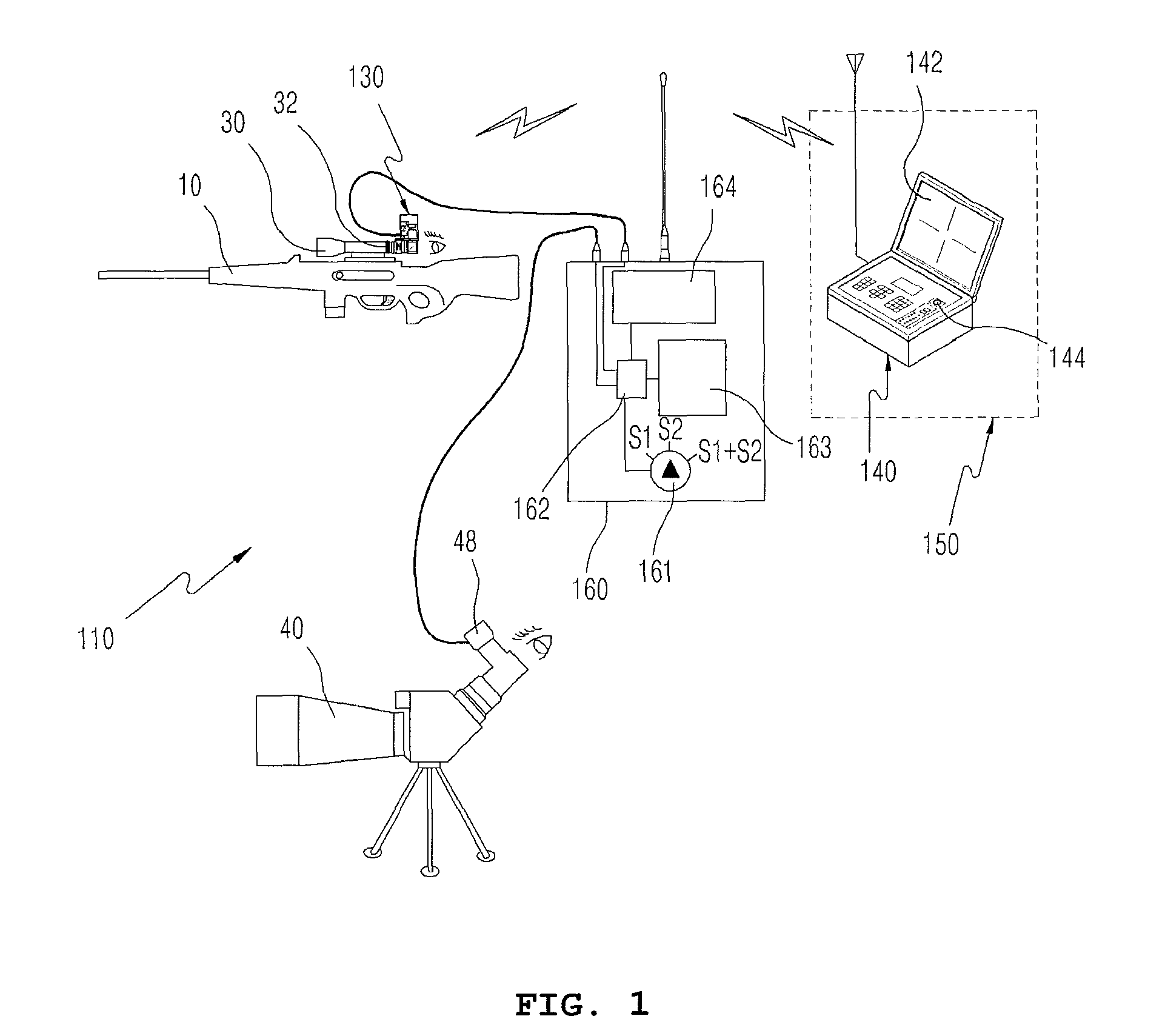
[0009]Accordingly, the present invention has been made keeping in mind the above problems occurring in the prior art, and an object of the present invention is to provide an integrated control system and method for controlling the aimed shooting of a sniper and the observation of a spotter, which form image signals corresponding to the same real-time moving images viewed by both a sniper who aims at a target with a firearm and will shoot at the target, and a spotter who widely grasps the safety of the place where the sniper is disposed and the surroundings of the target, and then observes a situation indicating whether the sniper has precisely hit the target at the time of shooting at the target while preventing the sniper's position from being leaked to the other party in such a way that image signals are formed by a sniper optical unit composed of an optical device and a camera which are attached to the outside of a sighting telescope mounted on the firearm of the sniper, and that image signals are formed by a spotter optical unit composed of an optical device and a camera which are attached to the outside of the observatory telescope of the spotter, so that two types of video captured by the sniper and the spotter can be selectively transmitted by the sniper or spotter by manipulating the channel switches of a wireless control transmission unit, and the video obtained by the two types of channels can be combined with each other using a multiplexer and can be transmitted in real time to the shooting controller of a commanding office located at a remote place through the wireless control transmission unit while the combined images are viewed on a small-sized monitor in a multi-screen division form, and which allows a commander in a commanding office to view the moving images so as to make a precise decision pertaining to shooting while sharing images of the spot in real time with the sniper and the spotter, and remotely controls shooting by controlling whether to release the trigger locking unit of the sniper's firearm at the remote place.
[0011]Further, the present invention provides an integrated control method of controlling aimed shooting of a sniper and observation of a spotter, comprising disposing a sniper who identifies a location of a target and will shoot at the target while aiming at the target with a firearm; allowing the sniper to aim at the target while viewing a magnified image of the target using a second eyepiece of a sighting camera unit attached to a sighting telescope provided on the firearm; allowing the sniper to identify the target using the second eyepiece and collect images of the target, transmitting part of the images of the target to a camera lens through a first prism of a reflection optical unit of the sighting camera unit, and allowing an image conversion module to convert the images of the target into digital video signals; locating the prism on a first side of a first eyepiece of the sighting telescope by which the sniper identifies the target, receiving images of the target corresponding to part of light and deflecting the images at an angle of 90° using the prism, allowing the camera lens to receive the images of the target, directly provided by the prism, allowing the image conversion module to convert analog video into digital video signals, and transmitting the digital moving video signals of the target to a shooting controller of a commanding office located at a remote place through a wireless control transmission unit; connecting a shooting unit connected to the wireless control transmission unit and a control unit located at the remote place to each other so that images / sound and shooting control signals therebetween are bidirectionally communicated in real time; outputting the images of the target on a Liquid Crystal Display (LCD) monitor of the shooting controller and enabling the images of the target to be viewed in real time by the control unit; the control unit determining whether to approve or disapprove shooting in such a way that a commander detects a precise location of the target and is aware of a time of shooting while viewing the images of the target on the LCD monitor of the shooting controller, and then transmitting a shooting approval signal to the wireless control transmission unit of the shooting unit; when the commander presses an approval button provided on a portion of the shooting controller, transmitting a shoot approval command to the sniper; when the control unit issues a shoot command, transmitting the shoot command to an electromagnetic control mounted on the firearm through the wireless control transmission unit; and the electromagnetic control transmitting a radio release signal in compliance with the shoot approval command, and retreating an electromagnetic lock of a trigger locking unit from its locked position, so that the sniper views a turn-on operation of a release indication lamp and shoots at the target in a locking release state by pulling the trigger.

Problems solved by technology

In addition, since the sniper reports the situation related to operations which have been made in an area outside the visible range of the commander, via voice communication using a radio, it is difficult for the commander located at the remote place to precisely grasp the current situation of the spot.
In this way, many problems related to complications and operations due to commands issued by the commander in the state in which he or she has not directly viewed the situation of a spot at the time of issuing the commands may occur in current systems in which the commander in the commanding office located at the remote place cannot precisely detect information about whether a sniper is located at a designated place securing a field of vision, whether the sniper has precisely identified the target, and whether the sniper has precisely aimed at the target using a sighting telescope and intends to shoot at the target, and in which the commander at the remote place merely listens to the description of the surroundings of the spot provided by a spotter, who performs his or her duty for reporting the situation of reconnaissance on the surroundings, using voice information based on a radio and issues a shoot command using the radio.

Method used


Image

  • Integrated control system and method for controlling aimed shooting of sniper and observation of spotter
  • Integrated control system and method for controlling aimed shooting of sniper and observation of spotter
  • Integrated control system and method for controlling aimed shooting of sniper and observation of spotter

Examples


Embodiment Construction

[0024]In order to accomplish the object, the present invention provides an integrated control system for controlling the aimed shooting of a sniper and the observation of a spotter, including a shooting unit, a sighting camera unit, an observation camera unit, a wireless control transmission unit, a shooting controller, a control unit, and a wireless image transmitter. The shooting unit is configured such that both a sniper and a spotter are located adjacent to each other, wherein the sniper aims at a target with a firearm and shoots at the target, and the spotter widely grasps the safety of the place where the sniper is disposed and the surroundings of the target and then observes, using an observatory telescope, the situation related to whether the sniper has precisely hit the target at the time of shooting at the target while preventing the position of the sniper from being leaked to the other party.

[0025]The sighting camera unit is mounted on one side of the eyepiece of a sighti...


PUM


Abstract

The present invention relates to a system and method for controlling the aimed shooting of a sniper and the observation of a spotter. At the same time that a sniper directly checks the shape of the target using a sighting telescope, a spotter observes the surroundings of the target using an observatory telescope. The sniper deflects images of the target using a prism, focuses the images, and converts the focused images into digital moving image signals. The spotter deflects images of the target using a prism, focuses the images, and converts the focused images into digital moving image signals. Two types of images can be selectively transmitted, or can be combined with each other using a multiplexer and transmitted to a shooting controller in a multi-screen division form. A commanding office can identify a precise target and make a decision pertaining to shooting.

Description

CROSS-REFERENCE TO RELATED APPLICATIONS[0001]The present application claims priority under 35 U.S.C. 119 of Korean Patent Application No. 10-2010-0003843, filed on Jan. 15, 2010, the disclosure of which is expressly incorporated by reference herein in its entirety.BACKGROUND OF THE INVENTION[0002]1. Field of the Invention[0003]The present invention relates, in general, to an integrated control system and method for controlling the aimed shooting of a sniper and the observation of a spotter, and, more particularly, to an integrated control system and method for controlling the aimed shooting of a sniper and the observation of a spotter, in which the sniper, who aims at a target with a firearm and will shoot at the target, directly checks the shape of the target using a sighting telescope while a spotter observes the surroundings of an area around the target using an observatory telescope, and then determines whether the current location of the sniper is safe and whether the target ha...

Claims


Application Information

Patent Timeline
Patent Type & Authority Patents(United States)
IPC IPC(8): F41G1/00
CPCF41A17/06F41A17/08F41G3/165F41G1/06F41G3/02F41A17/46
Inventor UHM, HYUN DUK
Owner KAISHOT CO LTD
Learn More