
Electronic sign having vertically hinged face panel doors

a technology of hinged face panel doors and electronic signs, applied in the field of electronic signs, can solve the problems of excessive spacing of pixels at the vertical seams between doors, inconvenient installation, and inability to meet the needs of users,

Active Publication Date: 2012-01-31
DAKTRONICS
View PDF39 Cites 72 Cited by
  • Summary
  • Abstract
  • Description
  • Claims
  • Application Information

AI Technical Summary

Benefits of technology

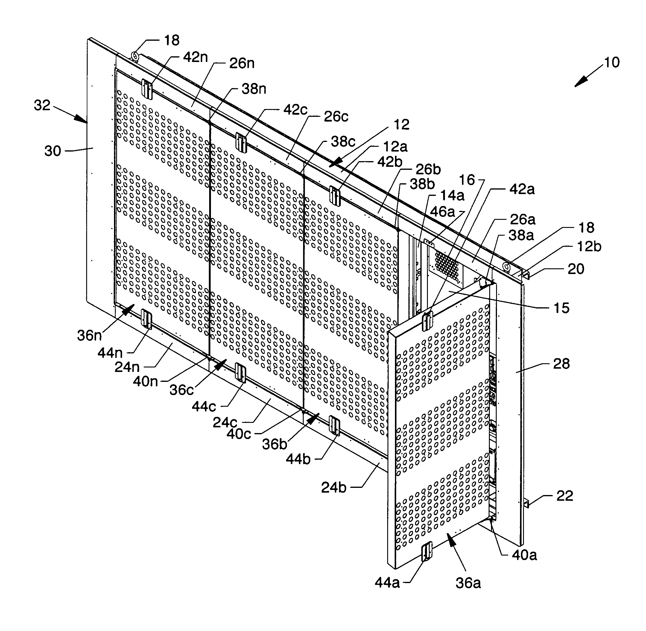
[0012]The invention is an electronic sign having vertically hinged face panel doors which allow for easy access to the inside of the sign from the front by the opening of one or more manageable vertically hinged face panel doors instead of one large and heavy face panel. Structure is provided to allow for a full matrix display where the face panel seams do not prevent the pixel spacing from being uniform across the broad matrix of the sign.
[0026]Still another significant aspect and feature of the present invention is the use of door stops which keep the wind from moving a face panel door when it is open.

Problems solved by technology

Most existing prior art front access full matrix signage used large single panel top hinged lift face panels that were ungainly and awkward to open and close, difficult to seal against the elements, insects and the like, as well as involving an inordinate amount of time to gain access thereinto.
Other prior art devices used displays with multiple vertically hinged doors, but the pixels spacing at the vertical seams between doors was excessive due to large gaps between panels that allowed the doors to pivot open without incurring mutual door interference at adjacent door edges.
Weather sealing provided by this design was very poor as the weather seals were small and thin in order to promote close juxtaposition of pixels from door-to-door.
Because of the space required for hinges and brackets between the panels, full matrix displays larger then a few feet tall were not possible.
Other prior art devices utilized a panel the size of the whole display face that was horizontally hinged across the top which, because of shear size, was difficult to properly weather seal.
Other signage using vertical hinges included large gaps in the LED matrix due to the interceding projecting structure of the hinge hardware.

Method used


Image

  • Electronic sign having vertically hinged face panel doors
  • Electronic sign having vertically hinged face panel doors
  • Electronic sign having vertically hinged face panel doors

Examples


Embodiment Construction

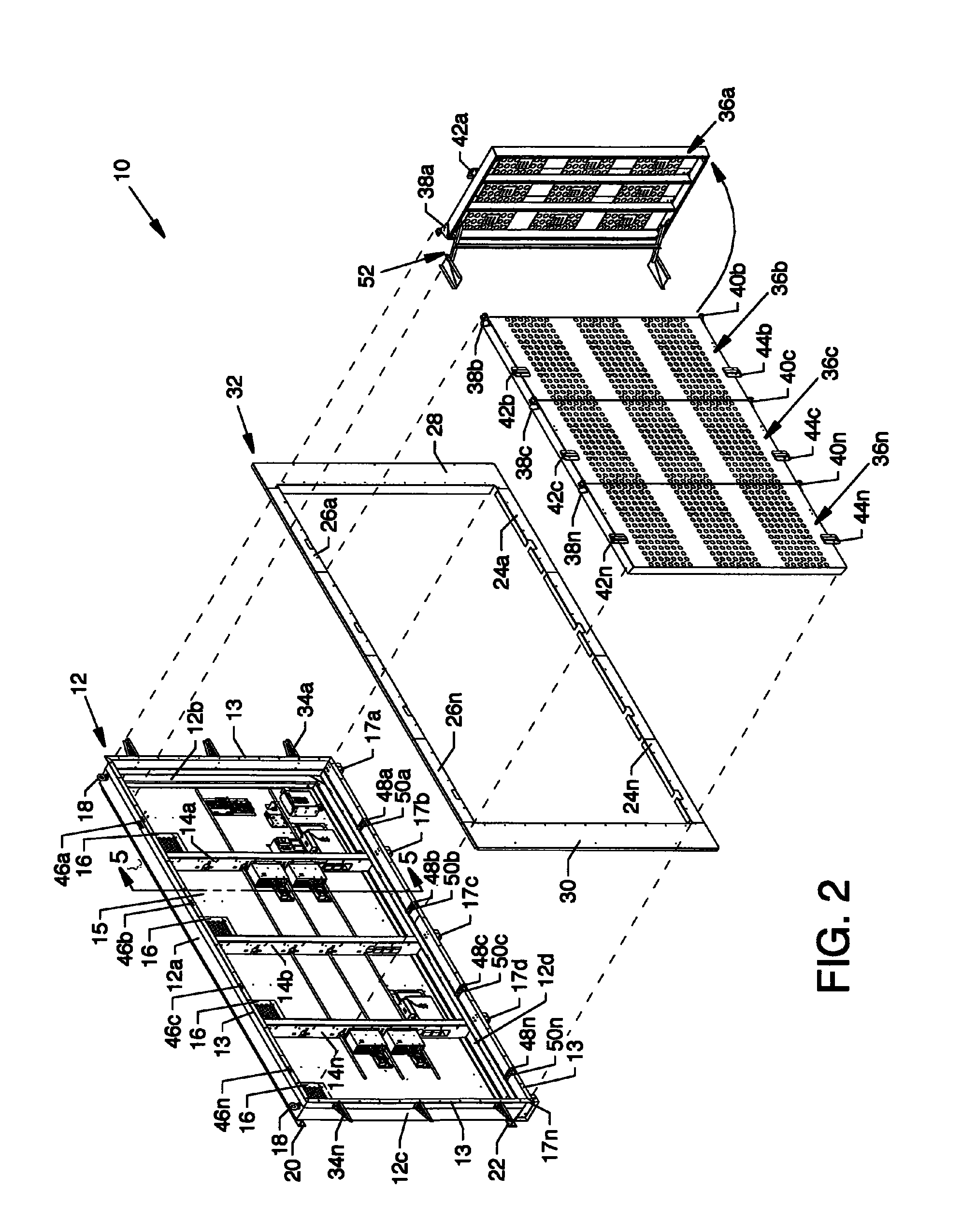
[0043]FIGS. 1, 3 and 4 are isometric views of an electronic sign 10 having vertically hinged face panel doors 36a-36n. FIG. 2 is a semi-exploded isometric view of the components of FIGS. 1, 3 and 4. FIG. 5 is a vertical cross section view through the frame 12 shown in FIGS. 1, 2, 3 and 4 through line 5-5 of FIG. 2. With reference to FIGS. 3, 4 and 5, and especially to FIGS. 1 and 2, fully or partially illustrated components of the invention are now described. The frame 12, to which multiple components are aligned and secured, includes configured channels including a top channel 12a, opposed end channels 12b and 12c, and a bottom channel 12d. A continuous lip 13 is formed by vertically aligned portions of the top channel 12a, opposed end channels 12b and 12c, and the bottom channel 12d. A plurality of vertically aligned formed channels 14a-14n, referenced in pending patent application Ser. No. 11 / 809,107 entitled “Electronic Sign Having a Formed Metal Cabinet” filed May 31, 2007, ext...


PUM


Abstract

An electronic sign having vertically hinged face panel doors which open individually about offset hinge assemblies and which aid in minimizing distorted seal compression. Individual door stop assemblies allow an operator to manageably open the face panel doors and to lock the face panel doors. In the open position, the face panel doors are protected from damage due to wind currents or gusts. The use of face panel doors having a parallelogram cross section profile allows for closely spaced face panel doors with a minimum panel-to-panel gap for uniform spacing and viewing of lighted pixel displays.

Description

CROSS REFERENCES TO RELATED APPLICATIONS[0001]This patent application is related to patent application Ser. No. 11 / 227,599 filed Sep. 15, 2005, entitled “Electronic Display Panel,” which is pending and which is a continuation-in-part of patent application Ser. No. 11 / 148,461 filed Jun. 9, 2005, entitled “Sign System,” which is pending.[0002]This patent application is also related to patent application Ser. No. 11 / 809,107 filed May 31, 2007, entitled “Electronic Sign Having A Formed Metal Cabinet,” which is pending.BACKGROUND OF THE INVENTION[0003]1. Field of the Invention[0004]The present invention is for an electronic sign, and more specifically, is for an electronic sign having vertically face panel doors.[0005]2. Description of the Prior Art[0006]Most existing prior art front access full matrix signage used large single panel top hinged lift face panels that were ungainly and awkward to open and close, difficult to seal against the elements, insects and the like, as well as invol...

Claims


Application Information

Patent Timeline
IPC IPC(8): G09F13/04G09F13/22
CPCG09F9/33G09F9/3026
Inventor SYRSTAD, JOHN W.
Owner DAKTRONICS
Learn More