
Feature point reduction for blood vessel biometric system

a biometric system and feature point technology, applied in the field of image processing methods and image processing apparatuses, can solve the problems of insufficient data reduction, image quality, and increase, and achieve the effect of accurate selection, suitably reduced information amount, and accurate elimination of feature points

Active Publication Date: 2012-01-24
MOFIRIA
View PDF9 Cites 5 Cited by
  • Summary
  • Abstract
  • Description
  • Claims
  • Application Information

AI Technical Summary

Benefits of technology

The method effectively reduces data amount while preserving identification information by simplifying the outline and approximating the original form, improving the efficiency of biometrics authentication.

Problems solved by technology

Therefore, a point not becoming a feature component is often extracted, and it also often becomes insufficient in the amount of data reduction.
More particularly, this problem clearly exists as the image quality of a camera for imaging a blood vessel becomes higher.
On the other hand, in the blood vessel in the same image, if too many points are eliminated, a meaning as identification information may be lost.

Method used


Image

  • Feature point reduction for blood vessel biometric system
  • Feature point reduction for blood vessel biometric system
  • Feature point reduction for blood vessel biometric system

Examples


Embodiment Construction

[0057]Preferred embodiments of the present invention will be described with reference to the accompanying drawings:

(1) Overall Configuration of Authentication Apparatus According to this Embodiment

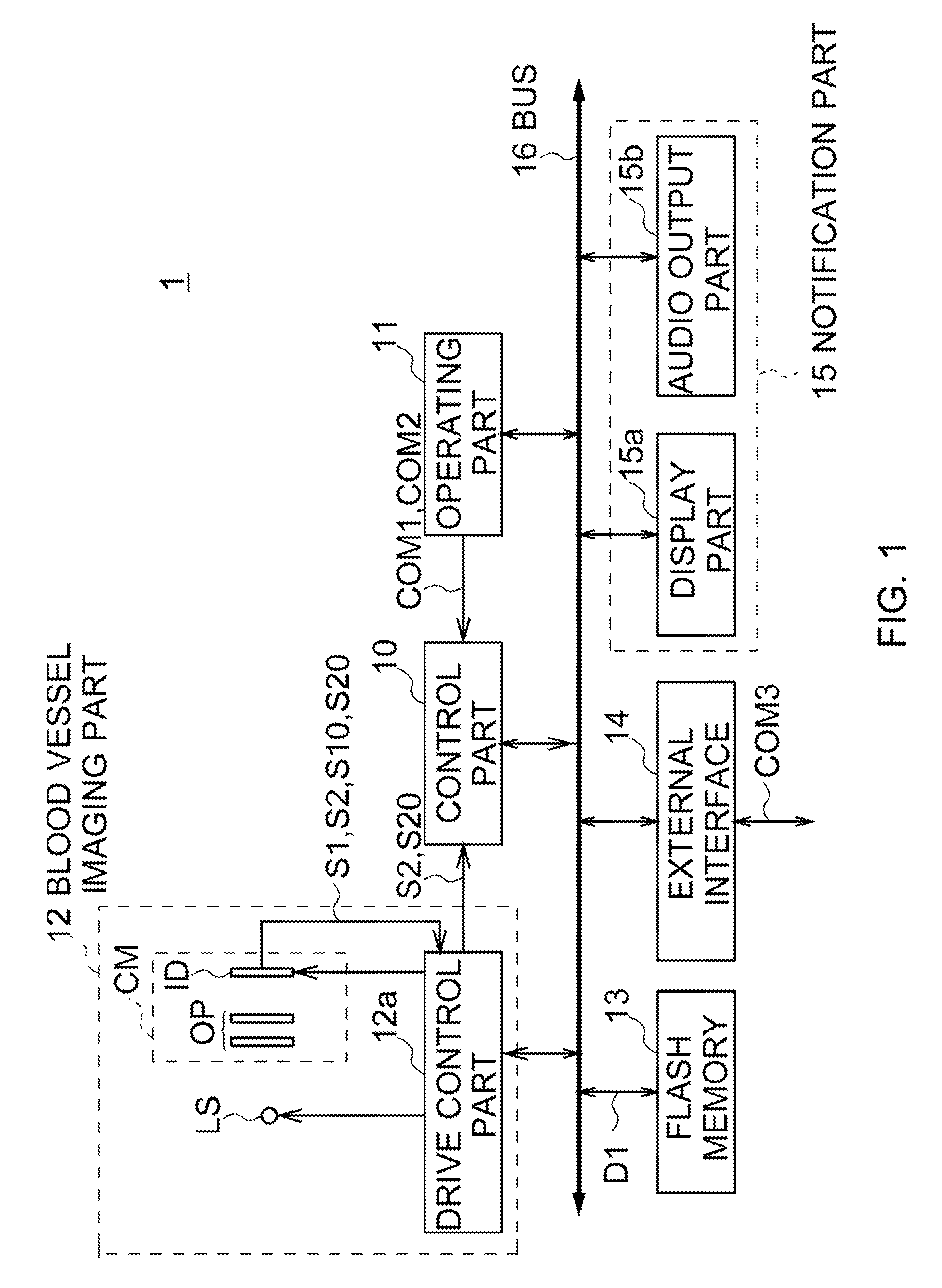
[0058]FIG. 1 shows the overall configuration of an authentication apparatus according to this embodiment. The authentication apparatus 1 is formed by that an operating part 11, a blood vessel imaging part 12, a flash memory 13, an interface for transmitting / receiving data to / from an external apparatus (hereinafter, this is referred to as an external interface) 14 and a notification part 15 are connected to a control part 10 respectively via a bus 16.

[0059]The control part 10 is a microcomputer including a central processing unit (CPU) for controlling the whole authentication apparatus 1, a read only memory (ROM) in that various programs and set information are stored, and a random access memory (RAM) serving as a work memory for the above CPU.

[0060]To the control part 10, an execution comm...


PUM

PropertyMeasurementUnit
intersection angleaaaaaaaaaa
thresholdaaaaaaaaaa
thresholdaaaaaaaaaa

Abstract

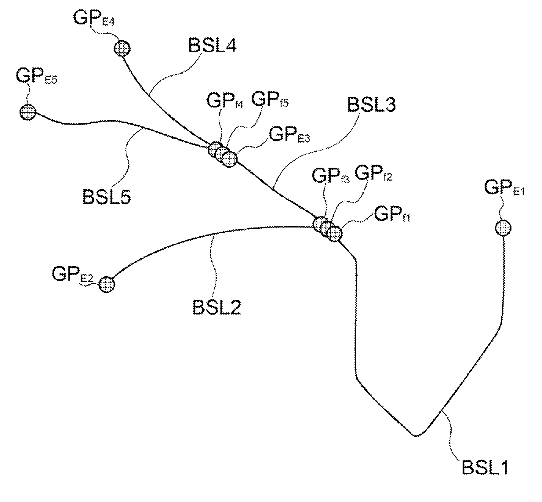
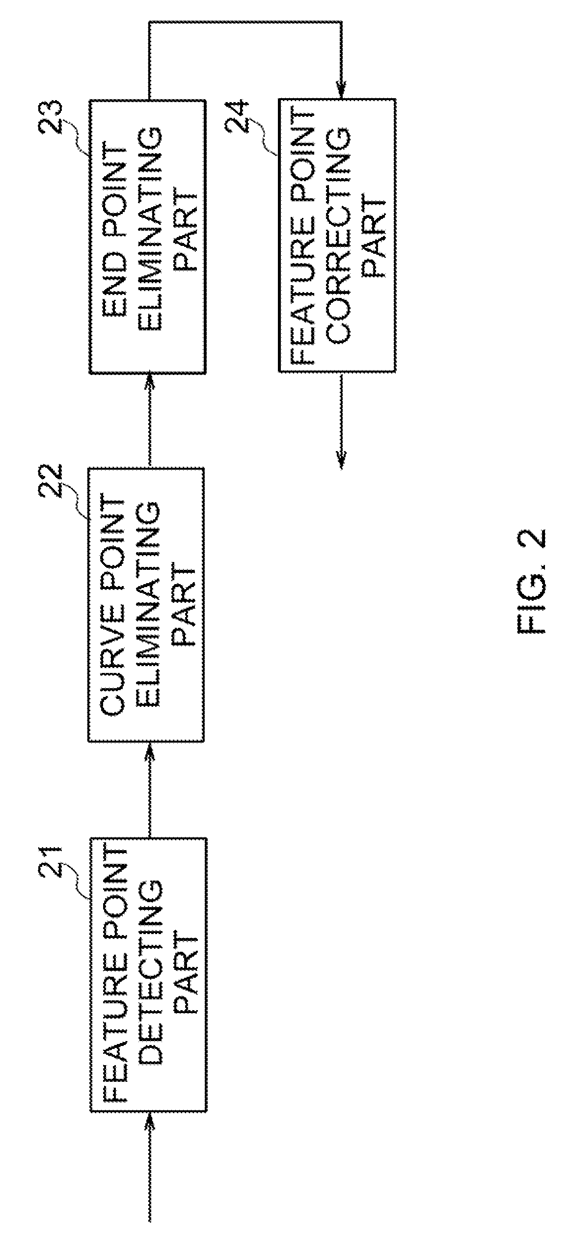
To suitably reduce data amount. For example, feature points from a branch point or an end point to the next branch point or an end point in a blood vessel line are set as a group. In the three feature points satisfying one of the condition that the absolute value of the outer product of vectors in continuous three feature points is smaller than an outer product threshold value, and the condition that a cosine in the above three feature points is smaller than a cosine threshold value, the middle one of the three feature points satisfying the other of the above conditions and being the smallest is eliminated, for every group.

Description

CROSS REFERENCE TO RELATED APPLICATION[0001]The present invention contains subject matter related to Japanese Patent Applications JP 2007-046089 filed in the Japanese Patent Office on Feb. 26, 2007 and JP 2006-207033 filed on Jul. 28, 2006, the entire contents of which being incorporated herein by reference.BACKGROUND OF THE INVENTION[0002]1. Field of the Invention[0003]The present invention relates to an image processing method, an image processing apparatus and a program therefor, and is applicable to a case of performing biometrics authentication, for example.[0004]2. Description of the Related Art[0005]Heretofore, as an object of biometrics authentication, there is a blood vessel. Generally, an authentication apparatus registers the image of blood vessels obtained by imaging in a memory as information to identify the living body that was imaged at the time, or determines whether or not the imaged person is the said registered person by comparing with the above registered image o...

Claims


Application Information

Patent Timeline
Patent Type & Authority Patents(United States)
IPC IPC(8): G06K9/00G06K9/46G06V10/34G01N21/35G01N21/359G06T3/00G06T7/00G06T7/60G06V10/46
CPCG06K9/44G06K9/48G06K2009/00932G06V40/14G06V10/34G06V10/46G06T7/40G06T1/00
Inventor ABE, HIROSHI
Owner MOFIRIA
Learn More