System for a linear drive

a linear drive and linear drive technology, applied in the field of systems, can solve the problems of difficult installation and high cost of t-pieces, and achieve the effect of simple and cost-effective wiring

Active Publication Date: 2012-01-24
SEW-EURODRIVE GMBH & CO KG
View PDF22 Cites 1 Cited by
  • Summary
  • Abstract
  • Description
  • Claims
  • Application Information

AI Technical Summary

Benefits of technology

[0003]Example embodiments of the present invention may provide simpler and more cost-effective wiring in drive units and systems.

Problems solved by technology

For this purpose, drive units are mostly connected via expensive plug-and-socket connectors.
These T-pieces are difficult to install and expensive, in particular when they must be usable and provide a high degree of protection in wet areas or even aseptic areas.

Method used


Image

  • System for a linear drive
  • System for a linear drive
  • System for a linear drive

Examples


Embodiment Construction

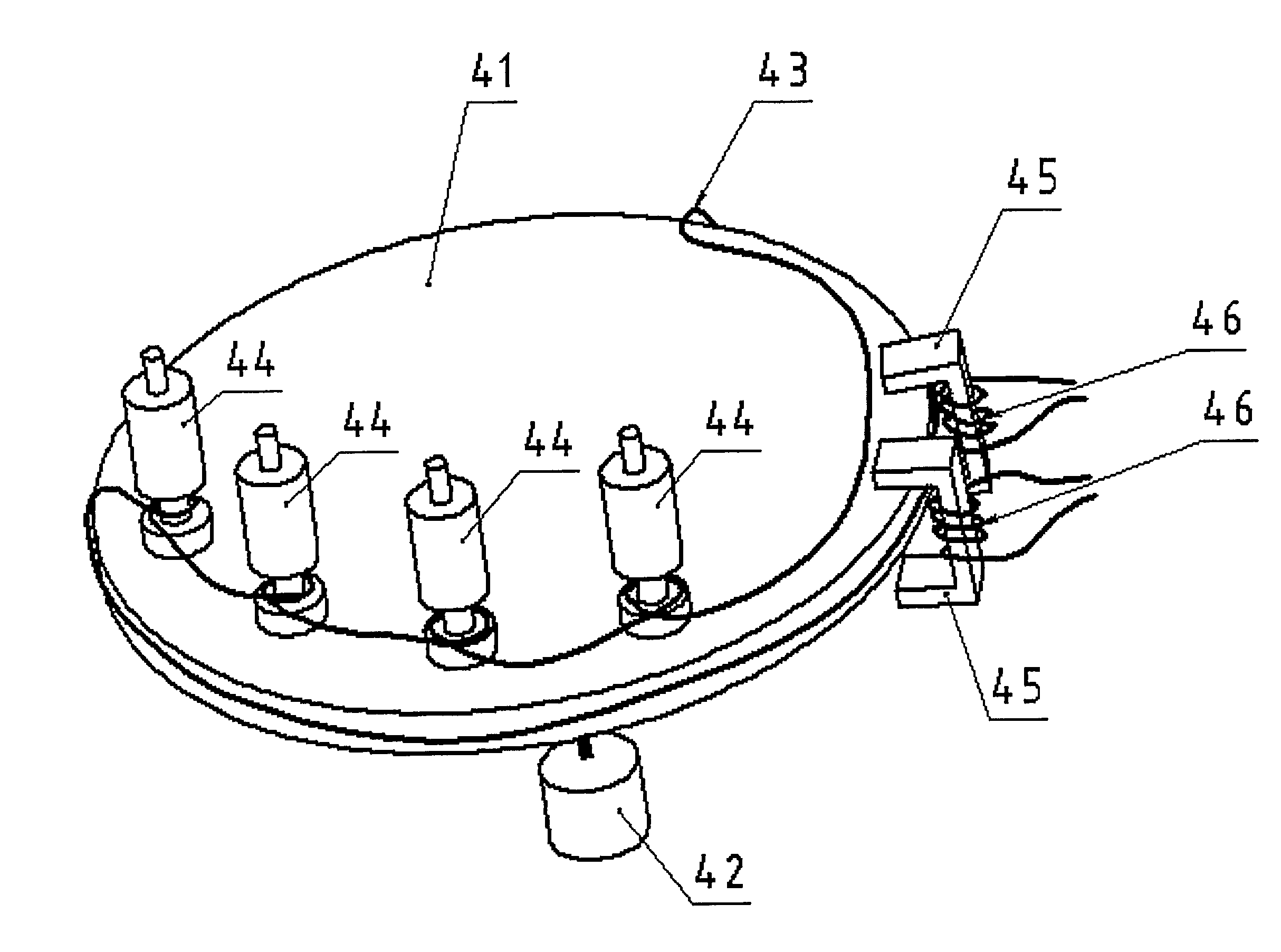
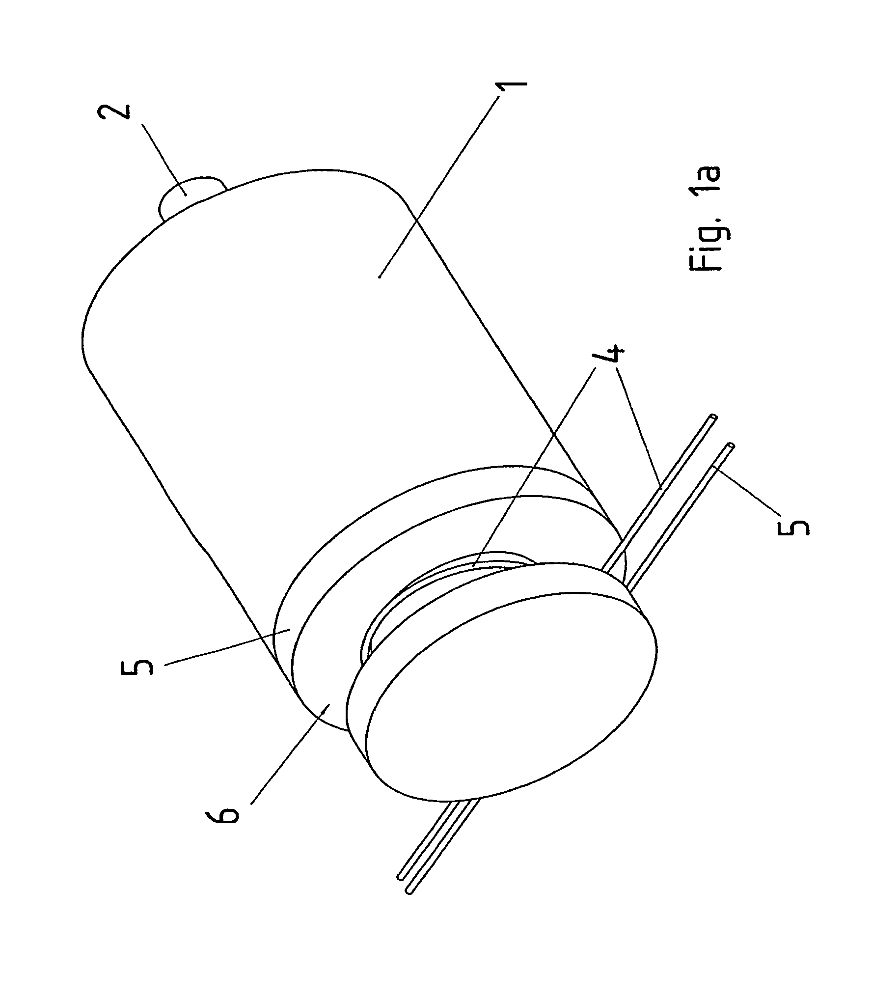
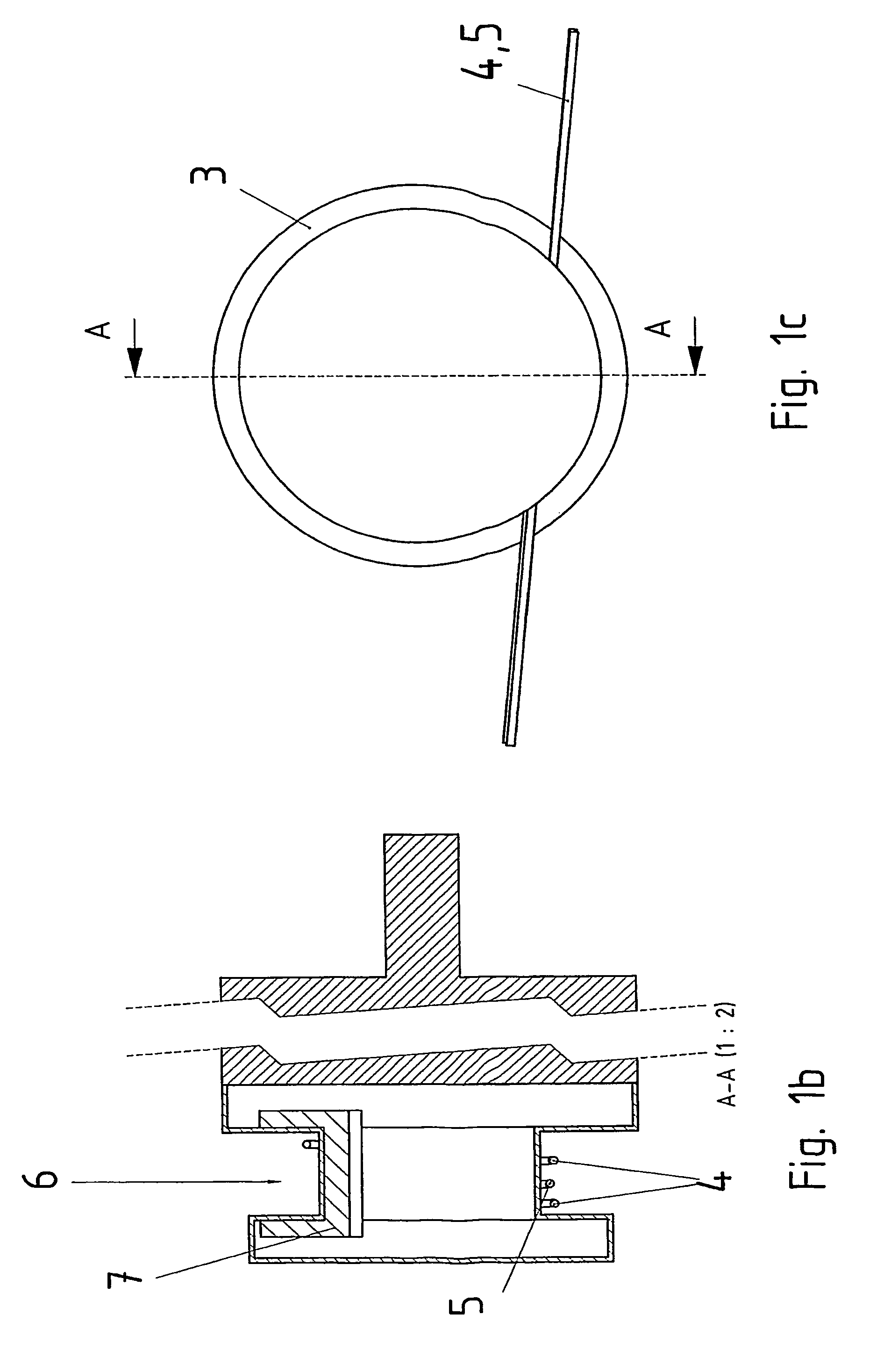
[0050]An isometric view, a sectional view, and a plan view of a drive unit according to an example embodiment of the present invention are illustrated in FIGS. 1a, 1b, and 1c. The drive unit includes an electric motor having a rotor shaft 2, which is surrounded by a housing 1. The electronic circuit for powering and controlling the electric motor is substantially protected by housing part 3, which has an indentation 6 in which a primary conductor is secured, using a winding loop. The return line, i.e., the second primary conductor, is only lead through, i.e., not wrapped around the drive unit.

[0051]Housing part 3 includes a core 7 having a U-shaped cross-section, around which a secondary winding is arranged that powers the electronic circuit. Therefore, the drive unit may be powered by the inductive coupling in a contactless manner, and is therefore galvanically separated from the primary circuit. The power supply of the drive unit may be disconnected rapidly and easily by unwinding...


PUM

PropertyMeasurementUnit
frequencyaaaaaaaaaa
poweraaaaaaaaaa
energyaaaaaaaaaa

Abstract

A system, whereby drive units on a movable part, e.g., a turntable or linear drive, are powered in a contactless manner via, in each instance, an inductive coupling to one or more primary conductors.

Description

FIELD OF THE INVENTION[0001]The present invention relates to a system.BACKGROUND INFORMATION[0002]In industrial systems, it is conventional that drive units can be powered from a network. For this purpose, drive units are mostly connected via expensive plug-and-socket connectors. In addition, the system or machine has a T-piece for each drive unit as an energy branch. These T-pieces are difficult to install and expensive, in particular when they must be usable and provide a high degree of protection in wet areas or even aseptic areas.SUMMARY[0003]Example embodiments of the present invention may provide simpler and more cost-effective wiring in drive units and systems.[0004]In the case of the system, features of example embodiments of the present invention include that it includes drive units, which are powered on a movable part, e.g., a turntable or linear drive, in a contact-free manner, using, in each instance, an inductive coupling to one or more primary conductors. In this conte...

Claims


Application Information

Patent Timeline
Patent Type & Authority Patents(United States)
IPC IPC(8): H01F21/06H02J5/00H02J17/00
CPCH02J5/005H02J50/402H02J50/12
Inventor SIMON, OLAFMAHLEIN, JOCHENSCHMIDT, JOSEF
Owner SEW-EURODRIVE GMBH & CO KG
Why Eureka
Try Eureka